182049 Viking Installation Manual - 第41页
semi automatic MACHI NE PREPARAT ION MACHI NE ASSEMBLY Chapter Issue 1 Oct 02 Instal lation Manual 5. 1 5 g. Careful ly lock bolt s A and B in position using the loc knuts prov ided. h. T ighten the three bolts on the f …
semi automatic
MACHINE PREPARATION
MACHINE ASSEMBLY
5.14 Installation Manual Chapter Issue 1 Oct 02
4. Carry out the following procedure to check and if required adjust the
transport rail levelling:
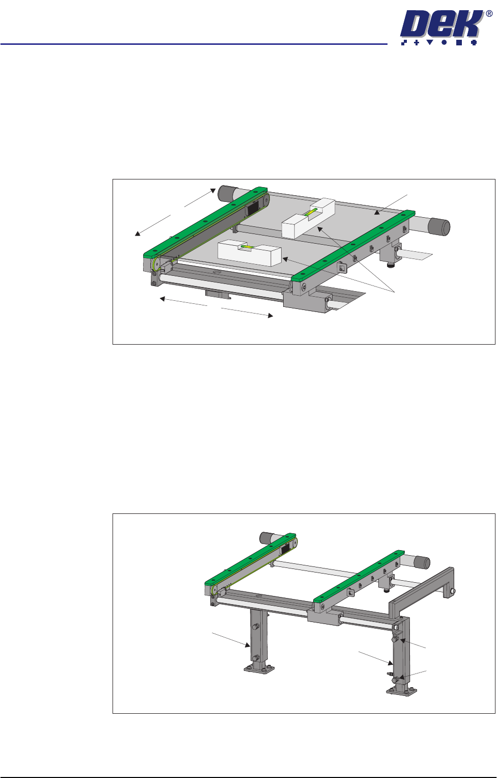
a. Adjust the transport rail width to approximately 250mm.
b. Place a Board Clamp Setting Plate Pt No 140403 onto the transport rail
belts.
c. Place a spirit level on top of the setting plate and check the levelness of
the rails in the X and Y planes.
d. If adjustment in the X plane is required, carry out Steps 4e - 4h.
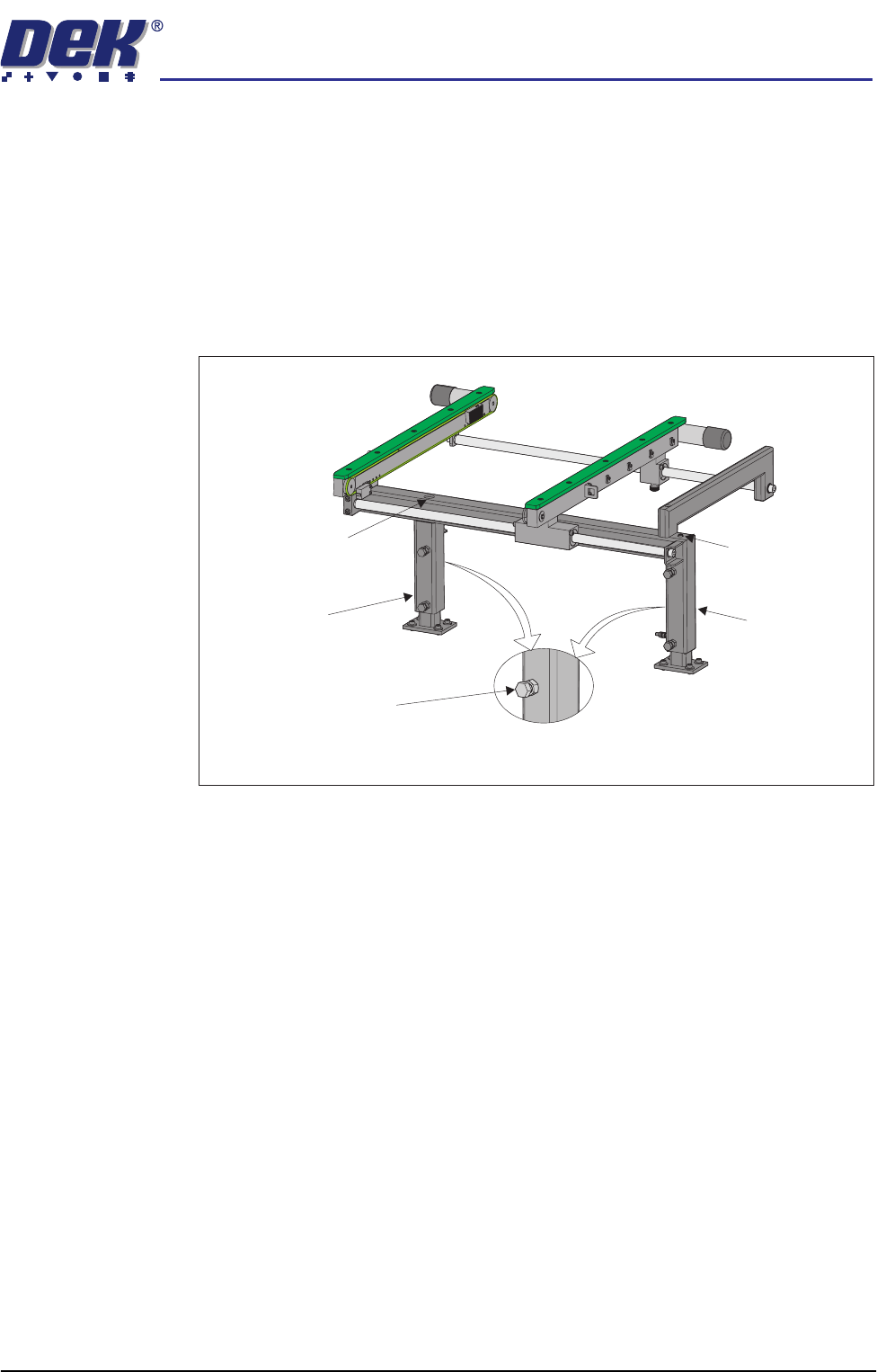
e. Loosen the three hexagonal headed bolts, two on the inner face and one
on the outer face of the front upright of the transport rail frame.
f. Using the two hexagonal headed bolts on the inner face of the rear upright
of the transport rail frame, carefully loosen or tighten the bolts to level the
assembly.
NOTE
Tightening bolt A and loosening bolt B raises the inboard end of the
transport rails. Loosening bolt A and tightening bolt B lowers the inboard
end of the transport rails.
X
Y
Board Clamp Setting Plate
Spirit Level
View on Transport Rail
Bolt A
Bolt B
Rear Upright of the
Transport Rail
Front Upright of the
Transport Rail
Rear view of Transport Rail
semi automatic
MACHINE PREPARATION
MACHINE ASSEMBLY
Chapter Issue 1 Oct 02 Installation Manual 5.15
g. Carefully lock bolts A and B in position using the locknuts provided.
h. Tighten the three bolts on the front upright of the transport rail frame and
repeat the check.
i. If adjustment in the Y plane is required, carry out Steps 4j - 4l.
j. Loosen the bolt C on the outer face of the appropriate upright.
k. Adjust the height of the upright by loosening or tightening the height
adjustment grub screw fitted to the top of the upright.
l. Tighten bolt C loosened in Step 4j and repeat the check.
Rear Upright of
Transport Rail
Front Upright of
Transport Rail
Rear view of Transport Rail
Bolt C on Outer Face of
Upright of Transport Rail
Height Adjustment
Grub Screw
Height Adjustment
Grub Screw
semi automatic
MACHINE PREPARATION
MACHINE ASSEMBLY
5.16 Installation Manual Chapter Issue 1 Oct 02
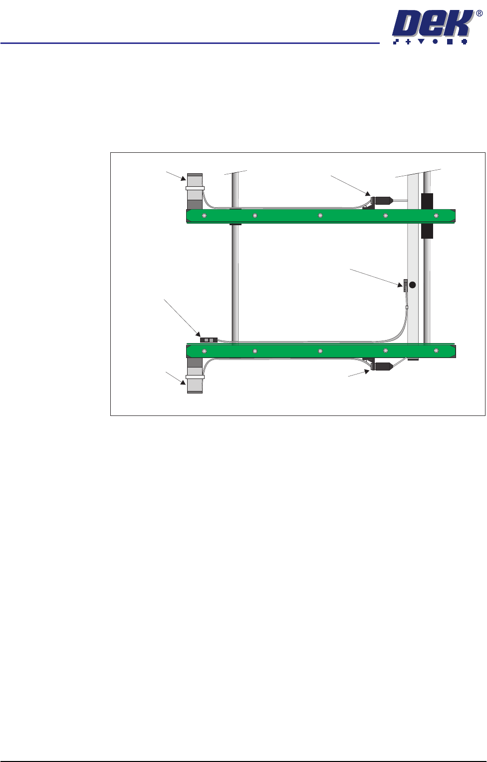
5. Connect the following connectors associated with the transport rail assem-
bly:
• 8PL04 - Board at Left sensor
• 8PL41 - Transport rail front belt motor
• 8PL42 - Transport rail rear belt motor
6. Refit the left hand machine side panels removed in Step 1.
MMI Assembly NOTE
The transport rail assembly and front left side cover must be fitted before the
MMI assembly is fitted.
1. Remove the front panel of the machine.
2. Locate the ergo arm mount bracket at the front of the machine, above the
M24 crate.
K
E
YE
N
C
E
P
Z
-4
2
L
View on Top of Transport Rail Assembly
Board at
Left Sensor
Rear Belt
Motor
Front Belt
Motor
Connector 8PL04
Board at Left Sensor
Connector 8PL42
Rear Belt Motor
Connector 8PL41
Front Belt Motor