182049 Viking Installation Manual - 第49页
semi automatic MACHI NE PREPARAT ION MACHINE LEVELLIN G Chapter Issue 1 Oct 02 Instal lation Manual 5. 2 3 Initia l Levelling When the correc t height of t he machin e has been achieved, the four feet should now be adjus…
semi automatic
MACHINE PREPARATION
MACHINE LEVELLING
5.22 Installation Manual Chapter Issue 1 Oct 02
MACHINE LEVELLING
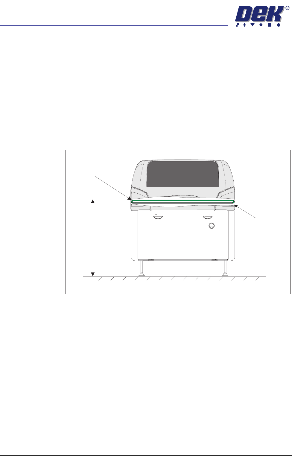
General Before operation, the machine height and level must be set.
Machine Height The height of the machine is adjustable from 820mm to 980mm which is
measured from the floor to the top of the transport belts, Machine Height figure
below refers. Ideally the machine should be set at its lowest position, with the
machine legs screwed in.
NOTE
To achieve reliable DEK SPC testing and Cp/Cpk results, the securing arrange-
ment of the four machine legs must be correct in accordance with the Mounting
Feet Arrangement diagram, (Major Relocation chapter - Unpacking section).
This arrangement increases the rigidity of securing the feet to the frame.
Figure 5-10 Machine Height
Height to Top of
Transport Belts
820mm to 980mm
View on Front of Machine
Transport Belts
Cutaway to
Show Belt
semi automatic
MACHINE PREPARATION
MACHINE LEVELLING
Chapter Issue 1 Oct 02 Installation Manual 5.23
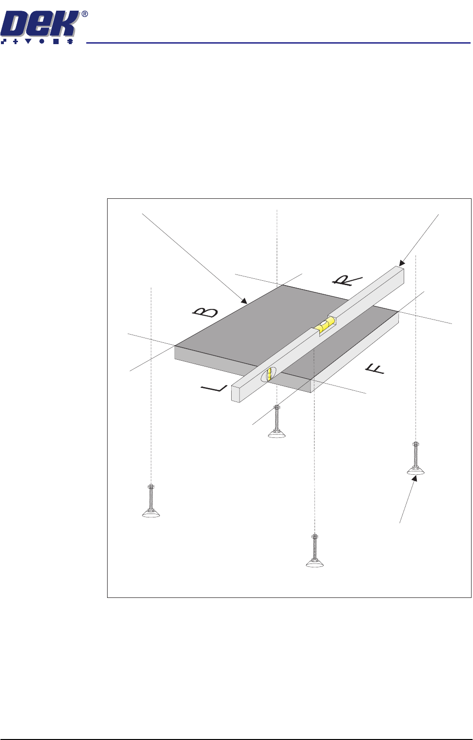
Initial Levelling When the correct height of the machine has been achieved, the four feet should
now be adjusted for correct level.
1. Place an engineering level on the tooling base plate facing Left (L) - Right
(R) or Back (B) - Front (F).
2. By carefully adjusting each of the four feet individually, level the machine so
that in each direction, Left (L) - Right (R) and Back (B) - Front (F), 0.004" per
foot (0.32mm/metre) is achieved.
3. Lock the feet using the locknuts on the adjusters.
Figure 5-11 Machine Levelling
Isometric View Showing Levelling of Tooling Base Plate
Tooling Base Plate
Engineering Level
Adjustable Mounting Feet
(4 positions)
semi automatic
MACHINE PREPARATION
SHOCK WATCHES
5.24 Installation Manual Chapter Issue 1 Oct 02
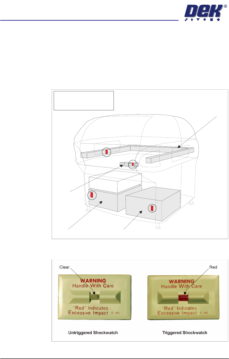
SHOCK WATCHES
A self adhesive shock watch (DEK Part No. 133517), is fitted in the vertical
plane on the machine in four places (Shock Watch Locations figure refers).
Check if the shock watches have been triggered, the indicator shows red, ('Drop
N Tell' Shockwatch figure overleaf refers).
NOTE
The machine should be fitted with four untriggered shock watches at all times.
Figure 5-12 Shock Watch Locations
Figure 5-13 Drop N Tell Shockwatch
Machine PC Machine Controller
Camera
Chase
NOTE
Shock Watches (4 positions)
shown circled