YSM10_Mainte_E.pdf - 第82页
3-15 3 Periodic maintenance items 2.2.2 Cleaning and lubricating the Y -axis guide 1 Pr epare for the cleaning and greasing. e 1. Press the emergency stop button to open the machine safety cover . 2. Place a square cloth…
3-14
3
Periodic maintenance items
4
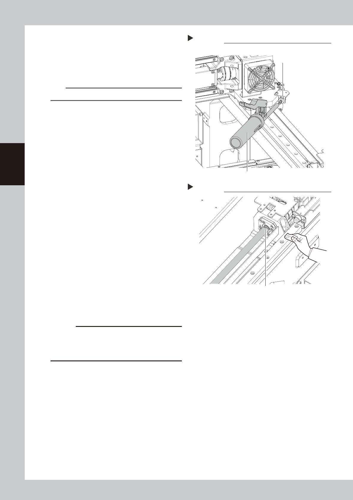
Inject the grease.
Using a grease gun (standard type), inject
the prescribed grease (NSL) at the 2 grease
nipples (1 each nipple for the left and right)
for the Y-axis guide.
53320-KMG-00
n
NOTE
Inject until the grease begins to seep out from the gap.
5
Wipe off the excess grease.
1. Grasp the carrying handle and move the
head unit backward.
2. Wipe all excess grease from the ball
screw and the ball screw end faces.
3. Move the head unit forward and wipe all
excess grease from the opposite-end ball
screw and the ball screw end faces.
53321-KMG-00
6
Perform a warm-up.
1. Remove the square cloth.
2. Reattach the anti grease splatter cover.
3. Close the machine safety cover and
cancel the emergency stop.
4. Press the [Warm Up] button on the
"Setup" screen to open the "Warm Up"
screen. Perform the warm-up operation
for approx. 8 minutes.
e
7
Check the grease condition.
1. After stopping the warm-up, press the
emergency stop button to open the
machine safety cover.
2. Remove the anti grease splatter cover
and wipe off grease which has collected
on the ball screw and the ball screw end
faces.
c
CAUTION
Repeat Steps 6 and 7 until grease accumulations no
longer occur. Beginning production with grease
accumulations present could cause the grease to
splatter.
8
Attach the anti grease splatter
cover.
Step 4
Grease nipple
Grease gun (standard type)
Injecting grease
Step 5
Wiping off the excess grease
Excess grease
3-15
3
Periodic maintenance items
2.2.2 Cleaning and lubricating the Y-axis guide
1
Prepare for the cleaning and greasing.
e
1. Press the emergency stop button to open the machine safety cover.
2.
Place a square cloth under the head unit
.
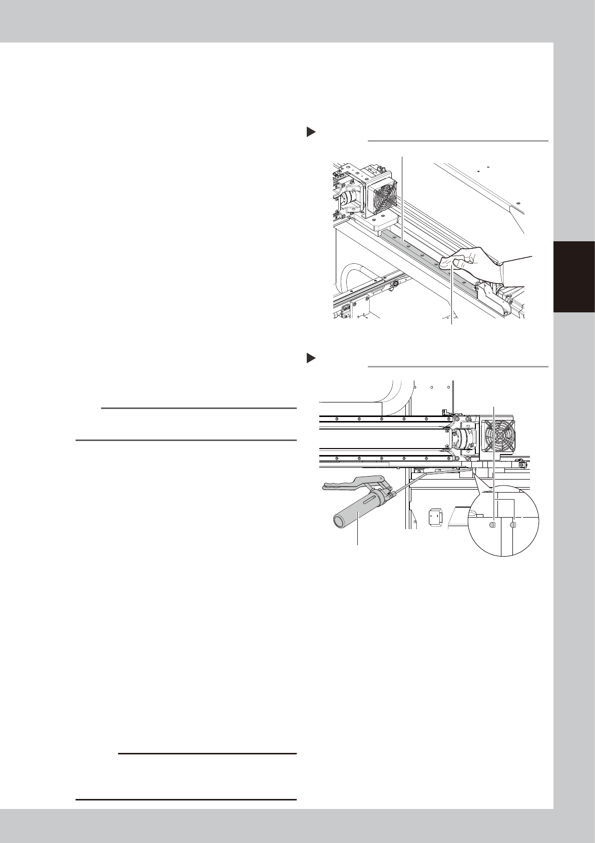
2
Clean the guide.
1. Grasp the carrying handle and move the
head unit backward.
2. Using a paper cloth (clean room type)
which produces no lint, wipe the old
grease and soiling from the entire guide.
3. Move the head unit to the opposite side,
then clean the opposite-side guide.
53322-KMG-00
3
Inject the grease.
Using a grease gun (bend type), inject the
prescribed grease (NSL) at the 4 grease
nipples (2 each nipples for the left and right)
for the Y-axis guide.
53323-KMG-00
4
Spread the grease.
Grasp the carrying handle and move the
head unit front and rear several times
manually to spread the grease.
n
NOTE
The grease injected through the nipple oozes to the
guide when moving the axis.
5
Wipe off the excess grease.
Wipe off the excess grease from both ends
of the guide.
6
Inject the grease again.
Repeat Steps 3 to 5 twice again.
After that, visually check that the grease is
applied to the entire guide.
7
Perform a warm-up.
1. Remove the square cloth.
2. Close the machine safety cover and
cancel the emergency stop.
3. Press the [Warm Up] button on the
"Setup" screen to open the "Warm Up"
screen. Perform the warm-up operation
for approx. 8 minutes.
e
8
Check the grease condition.
1. After stopping the warm-up, press the
emergency stop button to open the
machine safety cover.
2. Wipe off grease which has collected on
the guide end faces.
c
CAUTION
Repeat Steps 7 and 8 until grease accumulations no
longer occur. Beginning production with grease
accumulations present could cause the grease to splatter.
Step 2
Cleaning the guide
Cloth
Guide
Step 3
Grease nipple
Injecting grease
Grease gun (bend type)
3-16
3
Periodic maintenance items
2.3 Conveyor
2.3.1 Checking the conveyor sensor condition and operation
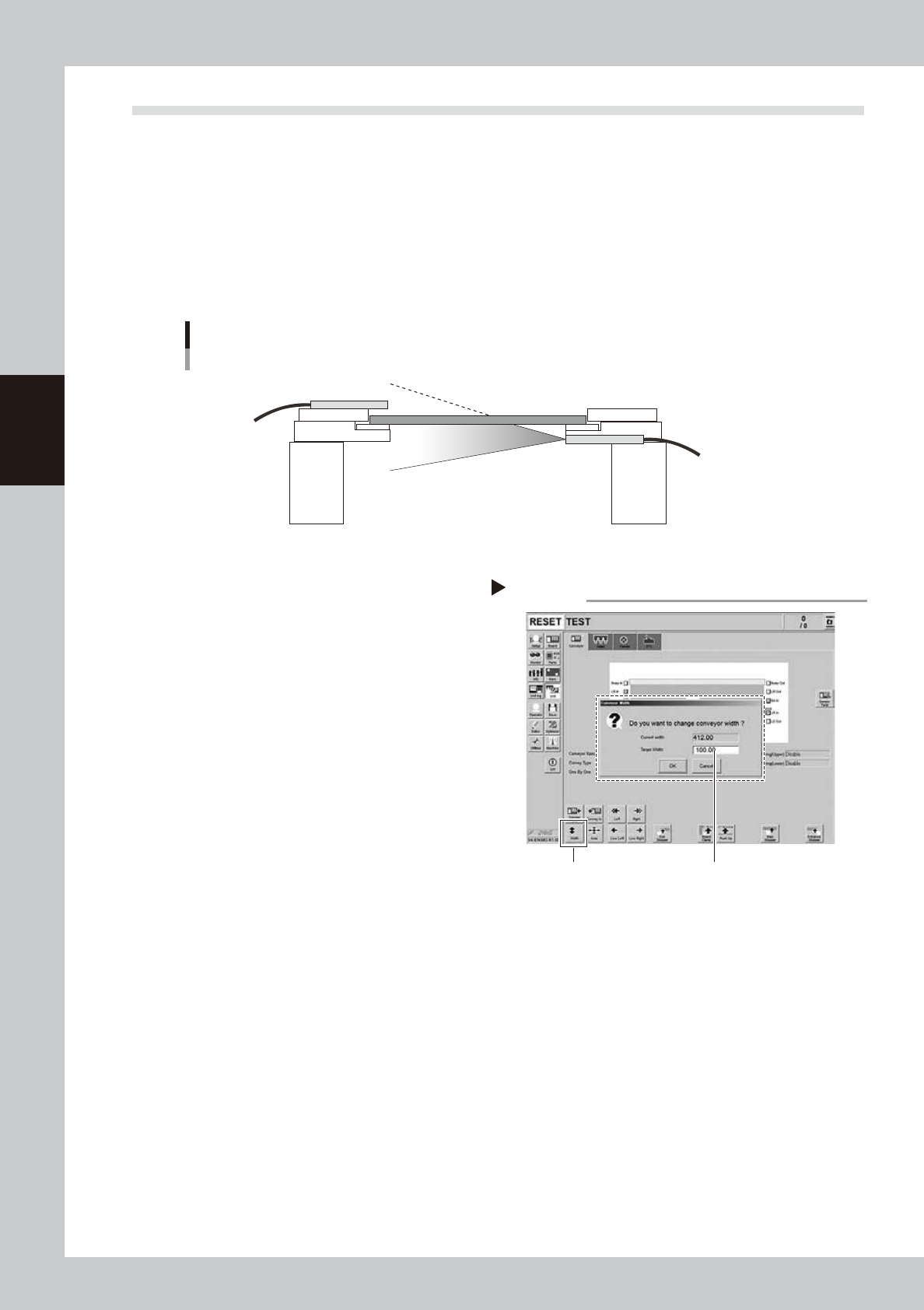
This machine uses a transmission type fiber sensor as the conveyor sensor.
As the conveyor width changes, the distance between the light emitting and light receiving sensors also
changes. Accordingly, the light receiving status of the sensor may change.
Therefore, a conveyor sensor tuning function is provided on this machine that stores the sensor light receiving
status after the conveyor rail width has been changed and automatically rewrites the sensor threshold value.
By changing the conveyor rail width periodically, you can check that the conveyor sensors and conveyor sensor
tuning operate correctly.
Checking the conveyor sensor condition and operation
Light emitting
Light receiving
53324-KMG-00
1
Prepare for work.
Check that there is no board on the
conveyor and that there is no push-up pin in
the conveyor movement range.
2
Change the conveyor width.
1. Open the [Unit] - [Conveyor] screen.
2. Press the [Width] button.
3. Enter the desired conveyor width and
press the [OK] button. The conveyor
width is changed to the specified width.
54301-KMG-00
3
Check that no error occurs.
When no error message appears after the
conveyor width has been changed, the
conveyor sensors operate correctly. So, no
further check is needed.
If an error occurred, perform "Conveyor sensor tuning" from Step 4.
Step2
[Width] button Enter desired conveyor width.
Changing the conveyor width