YSM10_Mainte_E.pdf - 第91页
3-24 3 Periodic maintenance items 4. Six-month inspection This section describes the maintenance work perfor med once every 6 months. 4.1 Recognition unit T he lighting unit may become dirty with dust due to the long-ter…
3-23
3
Periodic maintenance items
3.3.2 Cleaning the Machine rear side filter
The air intake filter for protecting the control unit is installed on the right of machine rear side.
1
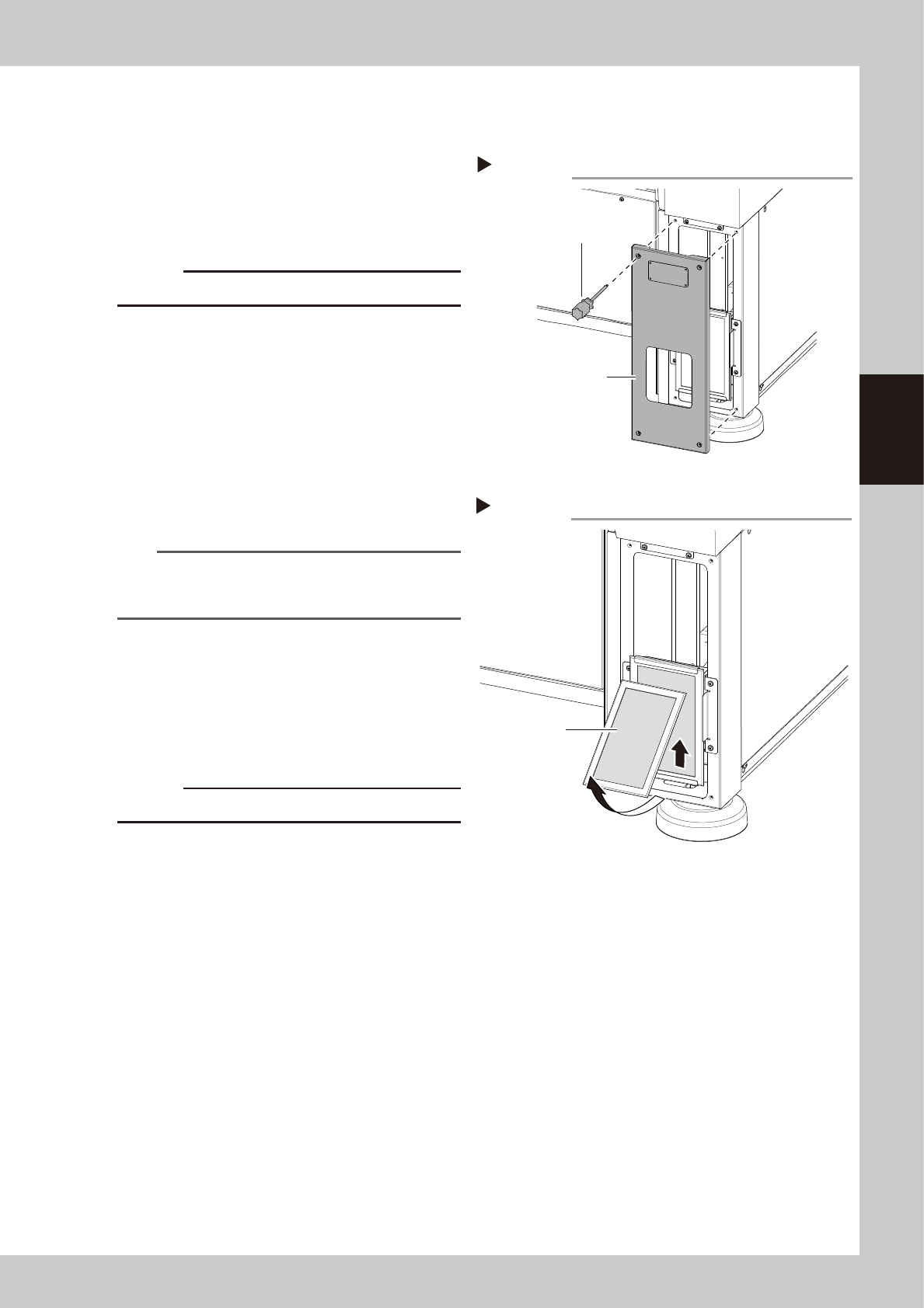
Open the cover.
Use a Phillips screwdriver to remove the 4
screws that mount the cover. It is not
necessary to remove screws.
53354-KMG-00
c
CAUTION
The ground wire is connected to the cover.
2
Detach the filter.
Push up the filter as shown in the figure on
the right and pull it out forward. When there
is no adjacent machine, the filter can be
detached by sliding it horizontally and
pulling it out.
53355-KMG-00
3
Clean the filter.
Use a vacuum cleaner or vacuum tool to
remove the dust sticking to the filter.
n
NOTE
If contaminants cannot be removed completely or if
the filter itself deteriorates, it is necessary to replace the
filter with a new one.
4
Return the filter to the original
position.
Reattach the filter by reversing its removal
procedure.
5
Return the covers to the original
positions.
c
CAUTION
Make sure not to catch cables when attaching covers.
Step 1
Opening the cover
Cover
(Lower right on the
rear of the machine)
Phillips screwdriver
Step 2
Detaching the filter
Filter
3-24
3
Periodic maintenance items
4. Six-month inspection
This section describes the maintenance work performed once every 6 months.
4.1 Recognition unit
The lighting unit may become dirty with dust due to the long-term use of the machine. Periodic cleaning is
recommended.
c
CAUTION
If trouble occurs with the lighting unit that was not improved by cleaning, contact YAMAHA or YAMAHA sales
representatives. Disassembly and cleaning of the lighting unit by the user will be excluded from the warranty.
4.1.1 Cleaning the fiducial camera
The fiducial camera is mounted on the head unit. The cleaning procedure for the camera's lighting unit is given
below.
c
CAUTION
Do not apply strong force or shock to the camera unit and lighting unit during cleaning. Optical axis adjustment might
become unreliable.
1
Move the head unit.
1. Press the emergency stop button to open
the machine safety cover.
2. Move the head unit forward.
2
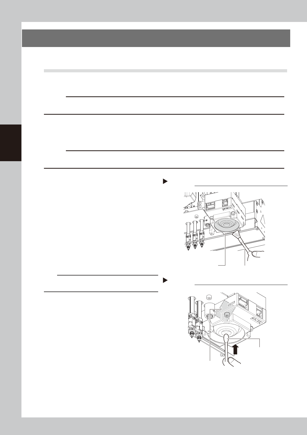
Clan the lighting unit.
Use a blower brush to remove the dust from
the lighting unit.
53332-KMG-00
3
Clean the reflector plate.
Use a cotton swab slightly dampened with
lens cleaner to clean the reflector plate side
as shown in the figure at right.
53333-KMG-00
TIP
The blower brush and lens cleaner are optional
purchase items.
Step 2
Fiducial camera lighting unit
Using a blower brush to remove dust
Blower brush
Step 3
Cotton swab dampened
with lens cleaner
Cleaning the reflector plate
Reflector plate
3-25
3
Periodic maintenance items
4.1.2 Cleaning the multi-camera lighting unit
The following describes the cleaning procedure for the multi-camera lighting unit.
c
CAUTION
Do not apply strong force or shock to the camera unit and lighting unit during cleaning. Doing so may damage the
glass components used in the camera unit.
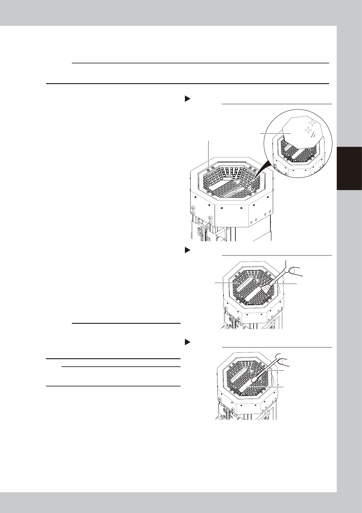
1
Detach the protective glass.
e
1. Press the emergency stop button to open
the machine safety cover.
2. Loosen 8 screws mounting the protective
glass with a phillips screwdriver to detach
the protective glass. It is not necessary to
remove the mounting screws.
53334-KMG-00
2
Wipe the protective glass with a
cloth.
Wipe off the top and bottom surfaces of the
protective glass with a cloth, into which a
few drops of lens cleaner are trickled.
53335-KMG-00
3
Clean the lighting.
Use a blower brush to remove the dust from
the lighting.
4
Clean the half-mirror.
Use a cotton swab dampened with a small
amount of lens cleaner to clean the half-
mirror.
53336-KMG-00
5
Reattach the protective glass.
Place the protective glass at its original
position and tighten the 8 mounting screws.
Tightening torque: 0.14N·m
c
CAUTION
Be careful not to tighten the mounting screw
excessively. If the mounting screw is tightened
continuously with a force exceeding the tightening
torque, the screw hole may be damaged.
TIP
The blower brush and lens cleaner are optional
purchase items.
Step 1
Detaching the protective glass
Protective glass
Mounting screw
Step 3
Cleaning the lighting
Lighting
Blower brush
Step 4
Cleaning the half-mirror
Half-mirror
Cotton swab dampened
with lens cleaner