00191021-02 - 第112页
3 Calibration Functions User’s Manual Test Program S ITEST 3.3 PCB Camera Calibration Software Version 403.xx Edition 12/ 97 3 - 8 NOTE The values thus dete rmin ed can be display ed afte r the com pletion o f the ca lib…
User’s Manual Test Program SITEST 3 Calibration Functions
Software Version 403.xx Edition 12/97 3.3 PCB Camera Calibration
3 - 7
3.3 PCB Camera Calibration
●
Carry out the preparatory steps proceeding as described in section 3.1.
●
In the "Gantry functions" display (see Fig. 0.3.4) click on the icon to switch to the
"PCB camera functions" display.
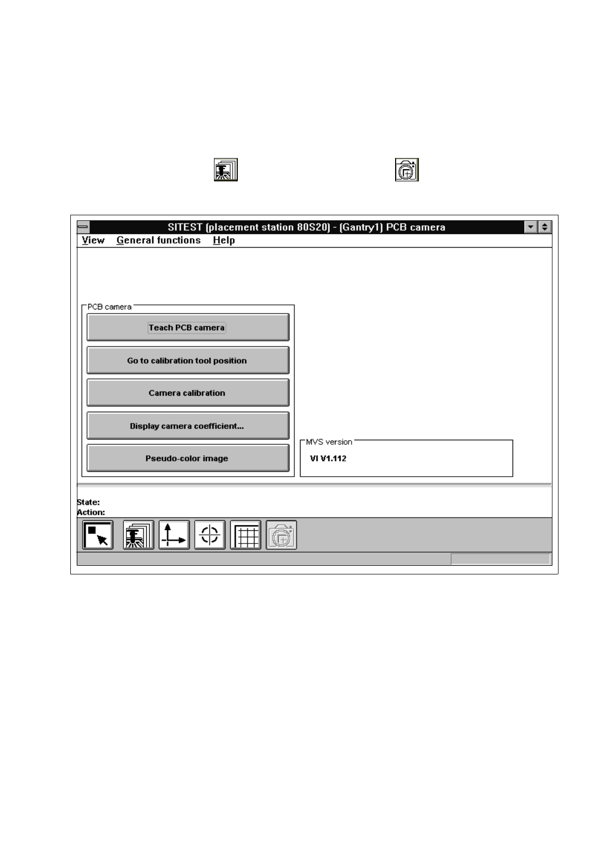
Fig. 3.3.1 "PCB camera functions" Display
Overview of the functions:
–
Teach PCB camera to call up the teaching functions
–
Go to calibration tool position to approach the fiducial position (calibration tool)
–
Camera calibration to calibrate the PCB camera
–
Display camera coefficient to display the PCB camera values determined
–
Pseudo-color image to switch the screen display to the pseudo-color image mode
to view the results of any illumination changes
●
Click on the
Camera calibration
button.
The calibration procedure is performed on the PCB camera of the active gantry.

3 Calibration Functions User’s Manual Test Program SITEST
3.3 PCB Camera Calibration Software Version 403.xx Edition 12/97
3 - 8
NOTE
The values thus determined can be displayed after the completion of the calibration procedure using
the
Display camera coefficient...
function.
●
Click on the icon to return to the main view.
User’s Manual Test Program SITEST 3 Calibration Functions
Software Version 403.xx Edition 12/97 3.4 RV Camera Calibration
3 - 9
3.4 RV Camera Calibration
●
Carry out the preparatory steps proceeding as described in section 3.1.
●
In the main view click on the icon or or to switch the screen display to the "RV head"
display (see Fig. 0.3.4) of the desired RV head.
●
Click on the icon to switch to the "RV head / RV camera" display.
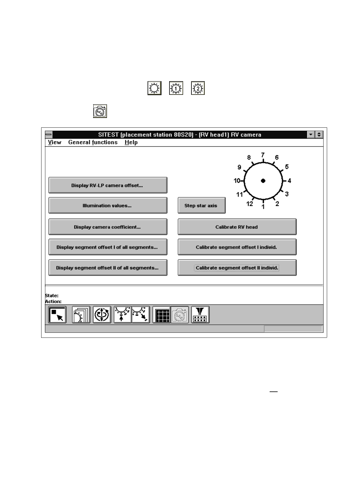
Fig. 3.4.1 "RV head / RV camera" Display
Overview of the functions:
–
Display RV-PCB camera offset... to display the offset values of RV-PCB camera
–
Illumination values... to display the illumination values
(Normally, the illumination values do not
need to be
changed. Changing the values in a non-expert manner will
lead to incorrect calibration results).
–
Display camera coefficient... to display the RV camera values determined
–
Display segment offset
I
of all segments... to display the x and y-offset values determined under
"Segment offset
I
"
–
Display segment offset
II
of all segments... to display the x and y-offset values determined under
"Segment offset
II
"
–
Step star axis to index the star