00191021-02 - 第113页
User’s Manual Test Program S ITEST 3 Calibration Functions Software Version 403.xx Edition 12/97 3.4 RV Camera Calibration 3 - 9 3.4 RV Camera Calibration ● Carry ou t the pr eparatory steps p roceedi ng as des cribed in…

3 Calibration Functions User’s Manual Test Program SITEST
3.3 PCB Camera Calibration Software Version 403.xx Edition 12/97
3 - 8
NOTE
The values thus determined can be displayed after the completion of the calibration procedure using
the
Display camera coefficient...
function.
●
Click on the icon to return to the main view.
User’s Manual Test Program SITEST 3 Calibration Functions
Software Version 403.xx Edition 12/97 3.4 RV Camera Calibration
3 - 9
3.4 RV Camera Calibration
●
Carry out the preparatory steps proceeding as described in section 3.1.
●
In the main view click on the icon or or to switch the screen display to the "RV head"
display (see Fig. 0.3.4) of the desired RV head.
●
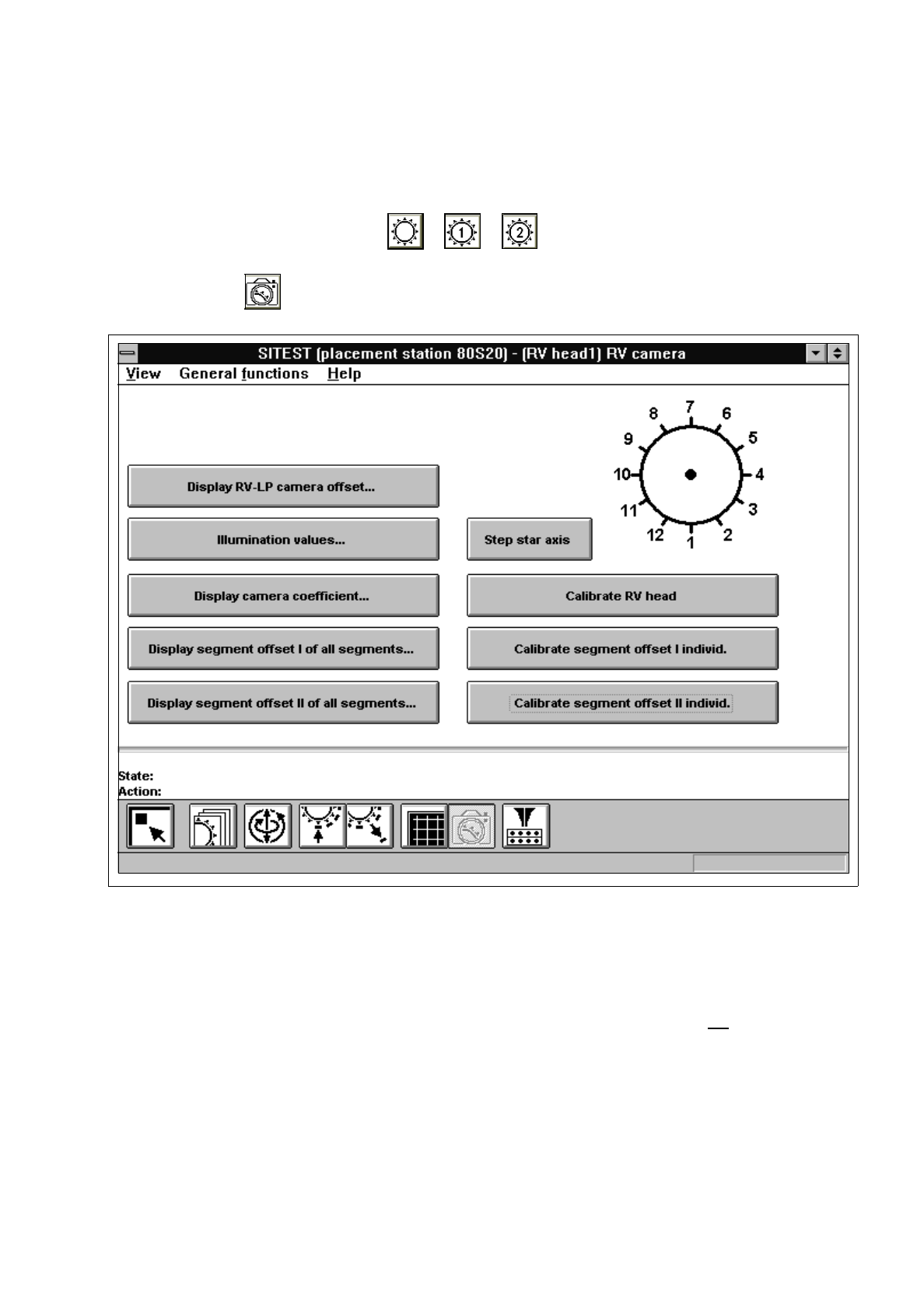
Click on the icon to switch to the "RV head / RV camera" display.
Fig. 3.4.1 "RV head / RV camera" Display
Overview of the functions:
–
Display RV-PCB camera offset... to display the offset values of RV-PCB camera
–
Illumination values... to display the illumination values
(Normally, the illumination values do not
need to be
changed. Changing the values in a non-expert manner will
lead to incorrect calibration results).
–
Display camera coefficient... to display the RV camera values determined
–
Display segment offset
I
of all segments... to display the x and y-offset values determined under
"Segment offset
I
"
–
Display segment offset
II
of all segments... to display the x and y-offset values determined under
"Segment offset
II
"
–
Step star axis to index the star

3 Calibration Functions User’s Manual Test Program SITEST
3.4 RV Camera Calibration Software Version 403.xx Edition 12/97
3 - 10
–
Calibrate RV head to calibrate the RV camera, segment offsets
I
and
II a
nd
the RV-PCB camera offset
–
Calibrate segment offset
I
individ. to determine segment offset
I
for the currently selected
segment
–
Calibrate segment offset
II
individ. to determine segment offset
II
for the currently selected
segment
●
Click on the
Calibrate RV head
button.
The calibration will be performed in the following sequence:
–
calibration of the RV camera
–
determination of segment offset
I
for all 12 or 6 segments
–
determination of segment offset
II
for all 12 or 6 segments
Segment offsets
II
are determined with the z-axis extended. The measurement is performed
repeatedly for each segment. The average value is calculated for each segment from the
measured values determined. The RV-PCB camera offset refers to segment
I
.
●
If you wish to determine segment offset
I
or
II
for a particular segment, first click on the
Step star axis
button repeatedly until the number of the desired segment (center sleeve) is displayed in the bottom
position.
●
Click on the
Calibrate segment offset I individ.
or
Calibrate segment offset II individ.
button.
The respective segment offset will be determined for the selected segment.
NOTE
The functions “Calibrate segment offset
I
individ.” and “Calibrate segment offset
II
individ.”
are only intended for error analysis purposes if the calibration of the RV head could not be carried out
successfully.
After the determination of individual segment offsets, the RV head must be completely recalibrated.
NOTE
After the completion of the calibration procedure it is possible to display the values determined during
the calibration of the RV camera by means of the
Display camera coefficient...
function.
The values determined for the segment offsets can be displayed using the
Display segment offset I
of all segments...
or
Display segment offset II of all segments...
, respectively.
●
Click on the icon to return to the main view.