00191021-02 - 第116页
3 Calibration Functions User’s Manual Test Program S ITEST 3.5 Calibration of t he Machine Zero Point Software Version 403.xx Edition 12/97 3 - 12 ● Click on t he Approach button in the "M achine z ero poi nt" …
User’s Manual Test Program SITEST 3 Calibration Functions
Software Version 403.xx Edition 12/97 3.5 Calibration of the Machine Zero Point
3 - 11
3.5 Calibration of the Machine Zero Point
NOTE
Verify that the calibration data for the RV camera, segment offset
II
(RV-PCB camera offset) and PCB camera
have already been determined.
On SIPLACE 80S machine types, the calibration of the machine zero point must be performed for both gan-
tries directly one after the other!
The MA zero point (measuring hole) is integrated on the fixed conveyor side in the same segment as the cali-
bration tool pocket (see Fig. 3.12.1 in section 3.12). This applies to all conveyor types!
●
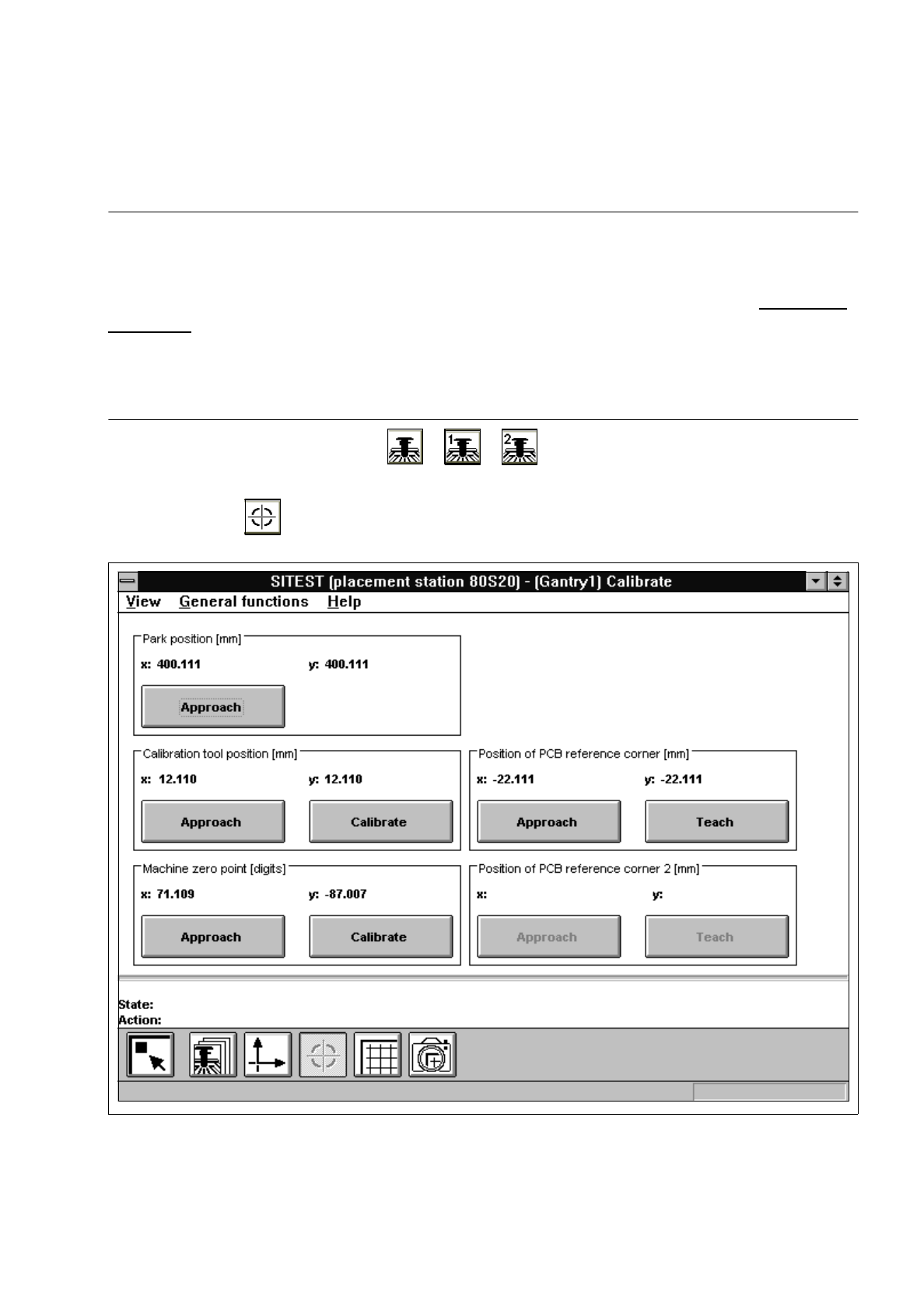
In the main view click on the icon or or to switch the screen display to the "Gantry"
display (see Fig. 0.3.4) of the desired gantry.
●
Click on the icon to switch to the "Calibrate positions" display.
Fig. 3.5.1 "Calibrate positions" Display

3 Calibration Functions User’s Manual Test Program SITEST
3.5 Calibration of the Machine Zero Point Software Version 403.xx Edition 12/97
3 - 12
●
Click on the
Approach
button in the "Machine zero point" field.
The active gantry moves the PCB camera over the measuring hole for the MA zero point.
The screen display is switched to the PCB camera.
●
Check whether the measuring hole for the machine zero point is visible in the camera’s field of view.
●
Press
ESC
to return the screen display to the normal program mode.
●
Click on the
Calibrate
button in the "Machine zero point" field.
The calibration of the machine zero point will now be performed. The position values for x and y are
displayed in the "Machine zero point" field.
●
Click on the icon to return to the main view.

User’s Manual Test Program SITEST 3 Calibration Functions
Software Version 403.xx Edition 12/97 3.6 Verification of the Calibration Tool Position
3 - 13
3.6 Verification of the Calibration Tool Position
●
In the main view click on the icon (for gantry 1 of SIPLACE 80S-20) or the icon (for the gantry
of SIPLACE 80F
4
)
to switch the screen display to the "Gantry" display (see Fig. 0.3.4).
●
Click on the icon to reach the "Calibrate positions" display (see Fig. 3.5.1).
●
Click on the
Approach
button in the "Calibration tool pos." field.
The active gantry moves the PCB camera over the calibration tool position. The screen display is
switched to the PCB camera.
●
Check whether the calibration tool fiducial is visible in the PCB camera’s field of view.
●
Press
ESC
to return the screen display to the normal program mode.