00191021-02 - 第12页
0 Introduction to the User Interface of the Test Program User ’s Manual Test Program S ITEST 0.2 Components of the User Interface Software Version 403.xx Edition 12/97 0 - 8 0.2.1 Menu Bar The menu bar o f the ma in view…
User’s Manual Test Program SITEST 0 Introduction to the User Interface of the Test Program
Software Version 403.xx Edition 12/97 0.2 Components of the User Interface
0 - 7
The user interface comprises the following components:
Title bar
The title bar displays the designation of the machine type for which the SITEST test program has been started
and the currently selected display, e.g. "SITEST (Placement station 80S-20) - Main view".
Menu bar
The menu bar lists the menus the contents (menu commands) of which may vary depending on the currently
selected view and machine type.
Work area
In this area, the control elements for the setting/activating of functions, the contents of activated menus and
submenus as well as general messages, error messages and other notices are displayed.
Control elements
By clicking on control elements with the left mouse button, actions can be triggered, options selected or
settings made. If control elements appear dimmed (light gray display) on the screen, the associated functions
are inappropriate for the current situation and cannot be selected.
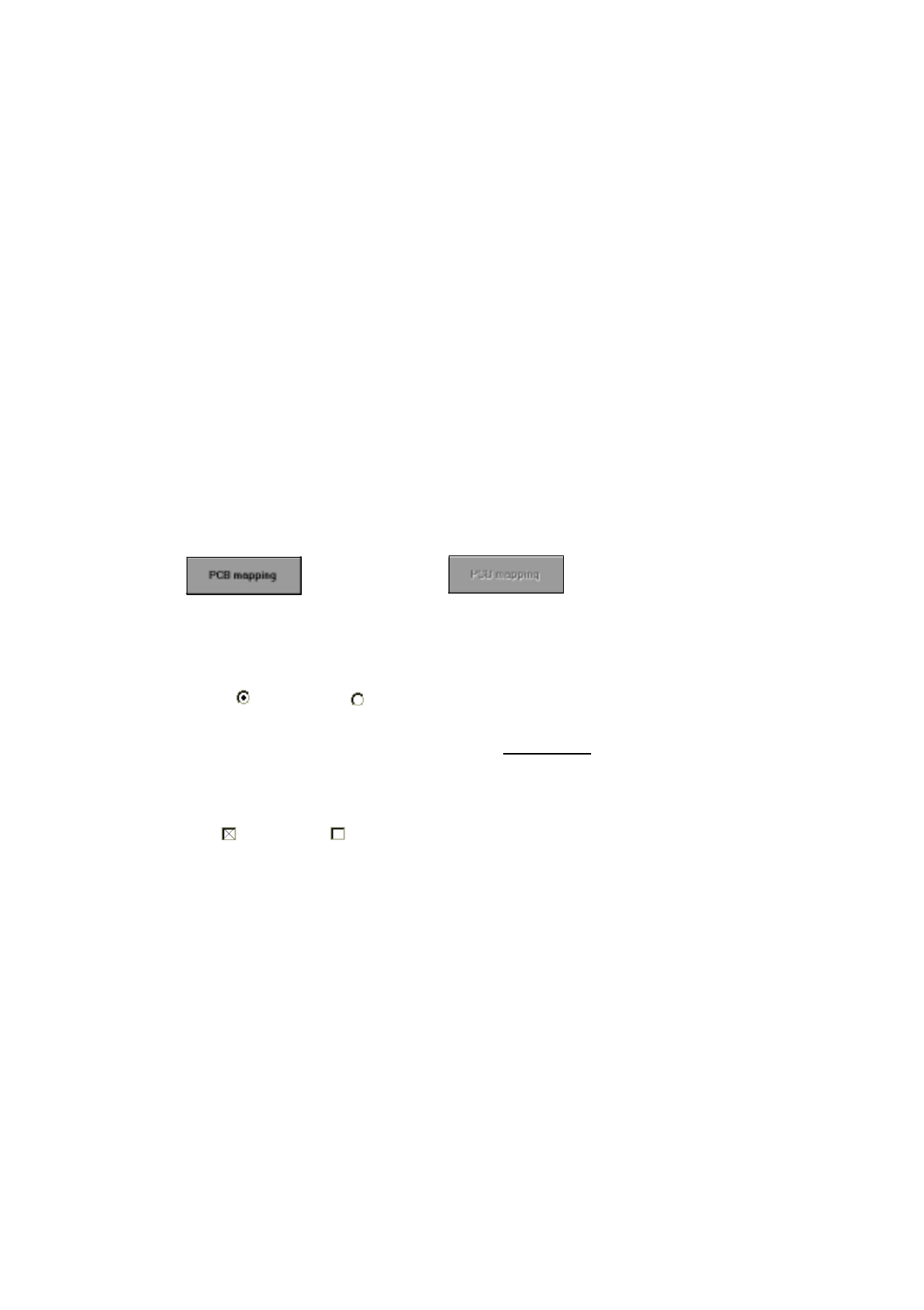
Button
(can be activated) (cannot be activated)
If a button is clicked on with the left mouse button, the function associated with that button can be acti-
vated, or a second window containing further options associated with that function can be opened.
Radio button
(activated) (not activated)
A radio button is used to select/set an option. If a radio button or the associated text in a group of radio
buttons has been activated with the left mouse button, no additional
radio button can be activated from the
same group.
Check box
(activated) (not activated)
A check box is used to select/set an option. If a check box or the associated text in a group of check boxes
has been activated with the left mouse button, it is possible to activate additional check boxes from the
same group.
Status bar
The status bar indicates current machine states, errors, etc.
Toolbar
This bar contains buttons by means of which you can switch between displays of the user interface enabling
you to carry out the required steps when working with the test program. If a button is clicked on with the left
mouse button, the display of the user interface is changed to that associated with the button. The button for
the currently activated display is then inactive.
Info bar
Here, short information on those menu entries or icons is displayed at which the mouse pointer is currently
directed.

0 Introduction to the User Interface of the Test Program User’s Manual Test Program SITEST
0.2 Components of the User Interface Software Version 403.xx Edition 12/97
0 - 8
0.2.1 Menu Bar
The menu bar of the main view display contains the menus "Mode", "View", "General functions", "Settings"
and "Help". All other displays do not contain the menus "Mode" and "Settings".
The "Help" menu contains the same menu commands in all displays (see sections 0.3.1 through 0.3.10).
NOTE
Some menu commands are followed by codes of function keys (e.g.
F2
) or key combinations (
A
LT
+
F4
) by
means of which the individual menu commands can be executed as well.
0.2.1.1 "Mode" Menu
This menu is exclusively displayed in the main view screen. The menu contains only one menu command by
means of which the termination of the test program can be initiated.
–
EXIT Alt+F4
●
Details on how to proceed are contained in section 0.1.2.
0.2.1.2 "View" Menu
Each of the menu commands contained in this menu permits you to switch to a different display. The menu
commands vary depending on the currently selected display (see sections 0.3.1 through 0.3.10). They always
correspond to the buttons in the toolbar. Thus, the operator is provided with the possibility of executing the
menu commands via the menu, the toolbar buttons, or by means of the function keys displayed on the menu.
Example:
–
Error F2
●
Click on
View
-->
Error
, or press function key
F2
.
The user interface switches to the "Error" display (see section 0.3.2, Fig. 0.3.3).
0.2.1.3 "General functions" Menu
This menu contains the menu commands by means of which the screen display can be switched to the indi-
vidual cameras available on the machine, as required. Moreover, the cycle mode can be activated or deacti-
vated as well.
–
Test functions...
This menu command is in this current version of the test program not functional.

User’s Manual Test Program SITEST 0 Introduction to the User Interface of the Test Program
Software Version 403.xx Edition 12/97 0.2 Components of the User Interface
0 - 9
–
Cycle mode... Alt+t
This causes the settings box for switchover to the cycle mode to open.
●
Details on how to proceed are contained in chapt. 1, section 1.4.
NOTE
The following 4 menu commands will vary depending on the machine type.
Machine type SIPLACE 80S-20
–
PCB camera P2 ALT+3
To switch the screen display to the PCB camera on gantry 2.
–
RV camera P2 ALT+4
To switch the screen display to the camera on revolver head 2.
–
PCB camera P1 ALT+5
To switch the screen display to the PCB camera on gantry 1.
–
RV camera P1 ALT+6
To switch the screen display to the camera on revolver head 1.
Machine type SIPLACE 80F
4
–
PCB camera ALT+5
To switch the screen display to the PCB camera on the gantry.
–
RV camera ALT+6
To switch the screen display to the camera on the revolver head.
–
IC camera ALT+7
To switch the screen display to the IC camera.
–
Flip-chip camera ALT+8
To switch the screen display to the flip-chip camera.
NOTE
Press the
ESC
key to switch the screen display back to the normal test program mode.