00191021-02 - 第125页
User’s Manual Test Program S ITEST 3 Calibration Functions Software Version 403.xx Edition 12/97 3.9 Calibration of t he IC Camera (SIPLACE 80F 4 ) 3 - 21 3.9 Calibration of the IC Camera (SIPLACE 80F 4 ) ● Carry ou t th…
3 Calibration Functions User’s Manual Test Program SITEST
3.8 Calibration of the IC Nozzle Changer (SIPLACE 80F4) Software Version 403.xx Edition 12/97
3 - 20
–
Garage number... to open the input box for the garage number
–
Pick-up height/rotat.angle... to display the values for the x and y-positions, the pick-up height and
the rotational angle of the current garage in the current magazine
(the data may be edited if required).
–
Nozzle data... to display for the current magazine the x, y and z-values determined
NOTE
The "Complete calibration" function is used if the nozzle changer is completely equipped with all 4 magazines.
If the nozzle changer is not
completely equipped with magazines, the x and y-values must be determined
separately for each magazine using the "Calibrate magazine" function.
●
Click on the
Complete calibration
button.
The PCB camera approaches the measuring holes of all magazines in the nozzle changer.
The x and y-values for each garage are calculated from the positions determined.
●
Click on the
Nozzle data...
button. A comparison of the setpoint values versus the actually determined
values in x and y-directions is displayed on the screen for each garage of the current magazine. The
z-position (pick-up height) is displayed in addition.
●
If the nozzle changer is not completely equipped with magazines, click on the
Magazine number...
button. The input box for the magazine number opens.
●
Enter the desired magazine number and confirm your entry by clicking on
Accept
.
●
Click on the
Calibrate magazine
button.
The PCB camera approaches the measuring hole of the selected magazine. The x and y-values for
each magazine compartment are calculated from the position determined.
●
To determine the pick-up height, enter the numbers of the desired garage and the desired magazine
prior to the calibration procedure using the
Garage number...
and
Magazine number...
functions.
NOTE
For the calibration of the pick-up height, a nozzle must be attached to the segment located at the
bottom and the selected garage must be empty.
●
Subsequently click on the
Calibrate pick-up height
button.
The pick-up height (z-position) determined is displayed in a dialog box after the calibration.
●
Acknowledge the dialog box by clicking on
OK
.
NOTE
The pick-up height must be determined for each magazine.
●
If you wish to check the results of the calibration, click first on the
Return
button and, after the nozzle
has been picked up, on the
Pick up
button.
●
Click on the icon to return to the main view.
●
On the menu bar click on
Settings
-->
Save machine data
. The data will now be saved.
User’s Manual Test Program SITEST 3 Calibration Functions
Software Version 403.xx Edition 12/97 3.9 Calibration of the IC Camera (SIPLACE 80F4)
3 - 21
3.9 Calibration of the IC Camera (SIPLACE 80F
4
)
●
Carry out the preparatory steps proceeding as described in section 3.1.
●
In the "IC head" display (see Fig. 0.3.6) click on the icon to switch to the "IC head /
IC camera" display.
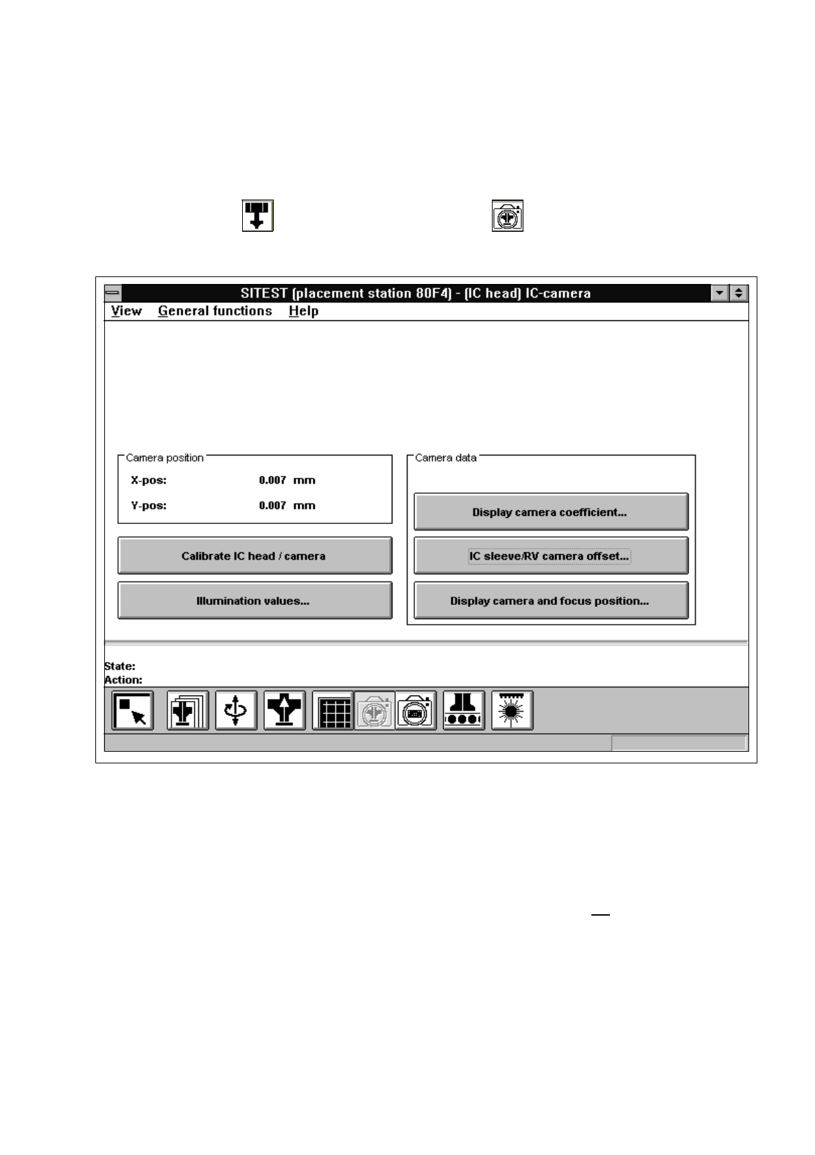
Fig. 3.9.1 "IC head / IC camera" Display
Overview of the functions:
–
Calibrate IC head / camera to calibrate the IC head and the IC camera
–
Illumination values... to display the illumination values
(Normally, the illumination values do not need to be changed.
Changing the values in a non-expert manner will lead to
incorrect calibration results).
–
Display camera coefficient... to display the IC camera values determined
–
IC sleeve/RV camera offset... to display the offset between IC sleeve and RV camera in x and
y-direction, determined during calibration
–
Display camera and focus position... to display the camera position and focus height determined
3 Calibration Functions User’s Manual Test Program SITEST
3.9 Calibration of the IC Camera (SIPLACE 80F4) Software Version 403.xx Edition 12/97
3 - 22
●
Click on the
Calibrate IC head / camera
button.
The complete calibration will now be performed.
●
If you wish to view the values determined after the completion of the calibration procedure, click on the
Display camera coefficient...
button.
●
If you wish to view the values for the camera position and focus height, click on the
Display camera
and focus position...
button.
A comparison of the current versus the previous camera data (camera position in x and y-directions
and focus height) is displayed.
NOTE
The x and y-values of the current camera position are also displayed in the "Camera position" field.
●
Click on the icon to return to the main view.