00191021-02 - 第132页
3 Calibration Functions User ’s Manual Test Program S ITEST 3.12 Measuring the Position of PCB Reference Corner I (and that of PCB Reference Corner II ) Software Version 403.xx Edition 12/97 3 - 28 Fig. 3.12.1 Location o…

User’s Manual Test Program SITEST 3 Calibration Functions
Software Version 403.xx Edition 12/97 3.12 Measuring the Position of PCB Reference Corner I (and that of PCB Reference Corner II)
3 - 27
3.12 Measuring the Position of PCB Reference Corner
I
(and that of PCB Reference Corner
II
)
NOTE
Verify that the calibration data for the PCB camera, segment offset
II
(RV-PCB camera offset) and machine
zero point have already been determined.
●
Load a PCB with a light-colored surface into the center conveyor using the conveyor functions (see
chapt. 2, section 2.5).
NOTE
Measuring the PCB reference corner positions on the SIPLACE 80S-20 machine type can only be per-
formed by means of gantry 1.
If a dual conveyor is installed on the machine, a PCB must be loaded on the right conveyor track ("PCB
conveyor 1") and
on the left conveyor track ("PCB conveyor 2") in order to be able to determine the position
of PCB reference corners
I
and
II
. To this end, select the desired conveyor in each case before
the respec-
tive PCB is loaded (see chapt. 2, section 2.5).
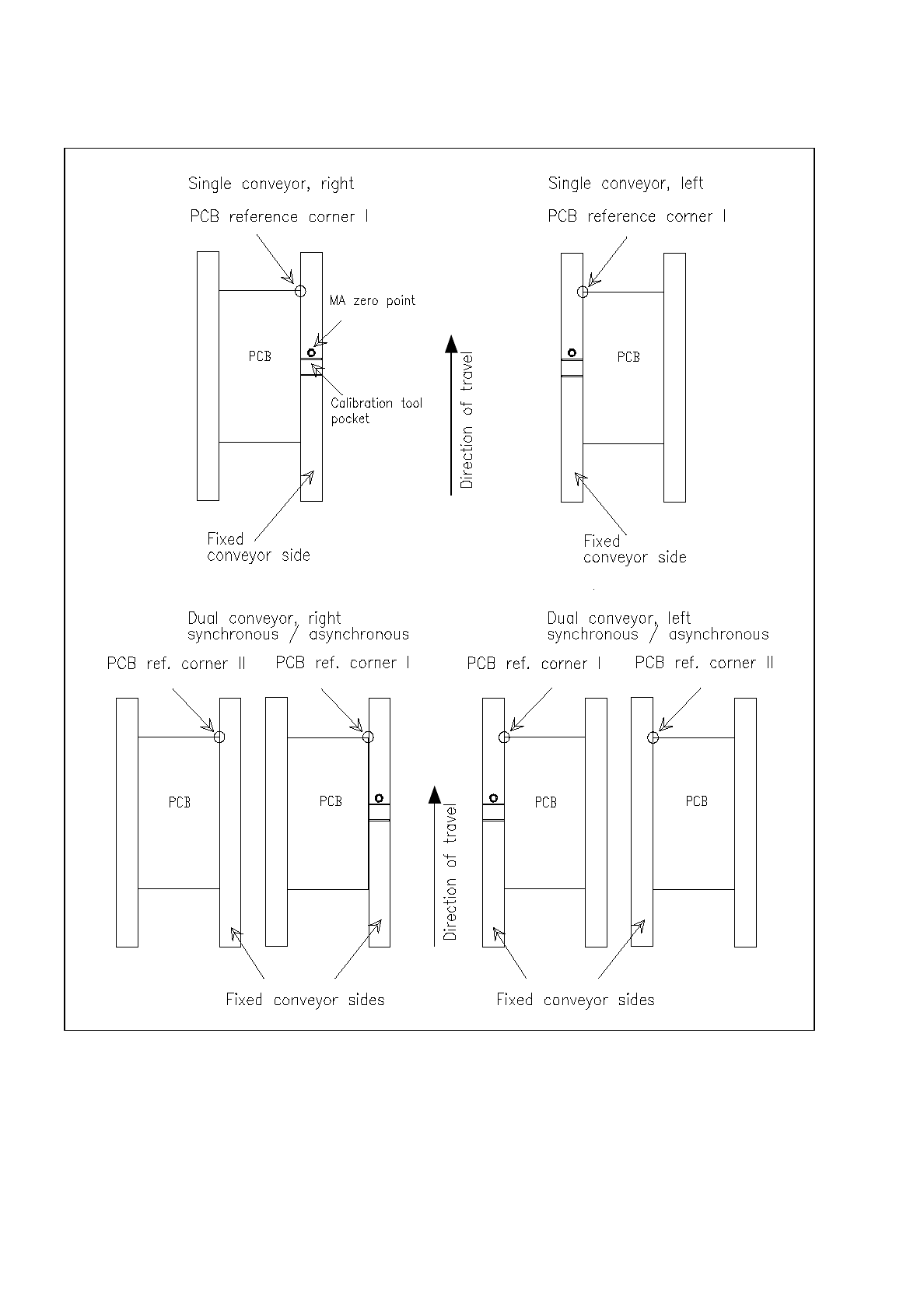
The location of the PCB reference corners
I
and
II
differs depending on the conveyor type used.
The following graphical display gives a schematic view of the positions of the PCB reference corners.
3 Calibration Functions User’s Manual Test Program SITEST
3.12 Measuring the Position of PCB Reference Corner I (and that of PCB Reference Corner II) Software Version 403.xx Edition 12/97
3 - 28
Fig. 3.12.1 Location of the PCB Reference Corners
User’s Manual Test Program SITEST 3 Calibration Functions
Software Version 403.xx Edition 12/97 3.12 Measuring the Position of PCB Reference Corner I (and that of PCB Reference Corner II)
3 - 29
●
In the main view click on the icon (for gantry 1 of SIPLACE 80S-20) or the icon (for the gantry
of SIPLACE 80F
4
)
to switch the screen display to the "Gantry" display (see Fig. 0.3.4).
●
Click on the icon to reach the "Calibrate positions" display (see Fig. 3.5.1).
●
To check the PCB reference corner position, click on the
Approach
button in the "Position of PCB ref-
erence corner" field. The gantry moves the PCB camera over the PCB reference corner position
I
.
The screen display is switched to the PCB camera.
●
Check whether the "PCB reference corner
I
" is visible in the PCB camera’s field of view.
●
Press
ESC
to return the screen display to the normal program mode.
●
To correct the position of the PCB reference corner, click on the
Teach
button in the "Position of PCB
reference corner" field.
The setting box for teaching the gantry opens, and the screen display is switched to the PCB camera
(for details on the procedure for moving the gantry during the teaching operation, refer to chapt. 1,
section 1.6).
●
Teach the PCB reference corner
I
using the cursor keys
↑↓ ← →
.
●
When teaching has been completed, press
ESC
to return the screen display to the normal program
mode.
●
Click on the
Cancel
button in the setting box. The taught position is accepted. The position values for x
and y are displayed in the "Position of PCB reference corner" field.
●
If a dual conveyor is installed on the machine, click on the
Approach
button in the "PCB reference
corner position 2" field.
The gantry moves the PCB camera over the PCB reference corner position
II
.
The screen display is switched to the PCB camera.
●
All further steps are to be performed in the same way as described for the PCB reference corner
I
.
●
Click on the icon to return to the main view.
●
Load the PCB(s) into the output conveyor using the conveyor functions (see chapt. 2, section 2.5).
●
Click on the icon to return to the main view.