00191021-02 - 第134页
3 Calibration Functions User ’s Manual Test Program S ITEST 3.12 Measuring the Position of PCB Reference Corner I (and that of PCB Reference Corner II ) Software Version 403.xx Edition 12/97 3 - 30
User’s Manual Test Program SITEST 3 Calibration Functions
Software Version 403.xx Edition 12/97 3.12 Measuring the Position of PCB Reference Corner I (and that of PCB Reference Corner II)
3 - 29
●
In the main view click on the icon (for gantry 1 of SIPLACE 80S-20) or the icon (for the gantry
of SIPLACE 80F
4
)
to switch the screen display to the "Gantry" display (see Fig. 0.3.4).
●
Click on the icon to reach the "Calibrate positions" display (see Fig. 3.5.1).
●
To check the PCB reference corner position, click on the
Approach
button in the "Position of PCB ref-
erence corner" field. The gantry moves the PCB camera over the PCB reference corner position
I
.
The screen display is switched to the PCB camera.
●
Check whether the "PCB reference corner
I
" is visible in the PCB camera’s field of view.
●
Press
ESC
to return the screen display to the normal program mode.
●
To correct the position of the PCB reference corner, click on the
Teach
button in the "Position of PCB
reference corner" field.
The setting box for teaching the gantry opens, and the screen display is switched to the PCB camera
(for details on the procedure for moving the gantry during the teaching operation, refer to chapt. 1,
section 1.6).
●
Teach the PCB reference corner
I
using the cursor keys
↑↓ ← →
.
●
When teaching has been completed, press
ESC
to return the screen display to the normal program
mode.
●
Click on the
Cancel
button in the setting box. The taught position is accepted. The position values for x
and y are displayed in the "Position of PCB reference corner" field.
●
If a dual conveyor is installed on the machine, click on the
Approach
button in the "PCB reference
corner position 2" field.
The gantry moves the PCB camera over the PCB reference corner position
II
.
The screen display is switched to the PCB camera.
●
All further steps are to be performed in the same way as described for the PCB reference corner
I
.
●
Click on the icon to return to the main view.
●
Load the PCB(s) into the output conveyor using the conveyor functions (see chapt. 2, section 2.5).
●
Click on the icon to return to the main view.

3 Calibration Functions User’s Manual Test Program SITEST
3.12 Measuring the Position of PCB Reference Corner I (and that of PCB Reference Corner II) Software Version 403.xx Edition 12/97
3 - 30
User’s Manual Test Program SITEST 3 Calibration Functions
Software Version 403.xx Edition 12/97 3.13 Measuring the Pick-Up Positions of Tracks 1 and 120
3 - 31
3.13 Measuring the Pick-Up Positions of Tracks
1 and 120
NOTE
Verify that the calibration data for segment offset
II
(RV-PCB camera offset), PCB camera and machine zero
point have already been determined.
●
Place the setting gauge onto track 1 or 120 of the component table to be measured.
NOTE
Prior to the measuring operation, check the component table surface underneath the setting gauge for
any unevenness or contamination.
●
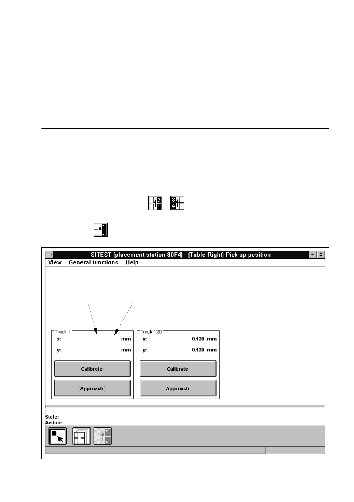
In the main view click on the icon or to switch the screen display to the "Table" display (see
Fig. 0.3.9) of the desired component table.
●
Click on the icon to switch to the "Pick-up position track 1 and track 120" display.
Fig. 3.13.1 "Pick-up position track 1 and track 120" Display
Current value
Old value
0.001 (0.001)
0.001 (0.001)