00191021-02 - 第44页
1 General Functions User’s Manual Test Program SITEST 1.3 Machine Configuration Software Version 403.xx Edition 12/97 1 - 8 NOT ES The se lection o f the conv eyor type a nd the fix ed conve yor side al so defines the lo…
User’s Manual Test Program SITEST 1 General Functions
Software Version 403.xx Edition 12/97 1.3 Machine Configuration
1 - 7
1.3 Machine Configuration
The configuration of the current machine is set in the "Settings" menu with the aid of the "Machine
configuration..." option.
For example, if a flux dispenser is installed on the machine, it must also be entered in the "Machine configura-
tion" so that the functions of the flux dispenser can be activated in the test program.
●
Click on the
Settings
menu and select the
Machine configuration...
option. The setting box
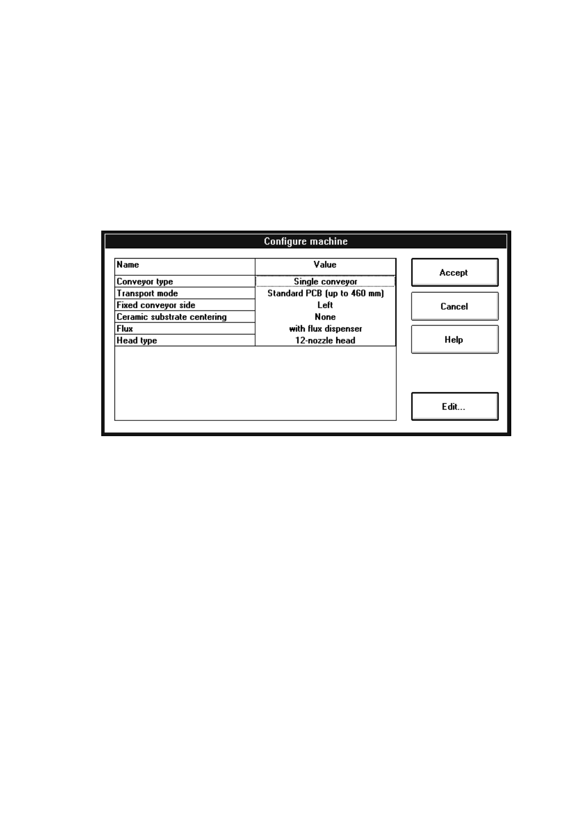
"Configure machine" opens.
The following configurations can be selected from:
–
Conveyor type
Single conveyor The calibration tool pocket with integrated measuring hole for
the MA zero point is located on the fixed conveyor side.
Synchronous dual conveyor On each conveyor track of the dual conveyor it is possible to
convey simultaneously a PCB of the same size to the center
conveyor.
The PCBs on the two conveyor tracks are processed as one
cluster.
The calibration tool pocket with integrated measuring hole for
the MA zero point is located on the fixed side of the conveyor.
Asynchronous dual conveyor PCBs loaded on any of the input conveyors are conveyed to the
unoccupied center conveyor at any given time during the place-
ment operation whereafter the assembly process is started.
The components to be placed and the width of the PCBs on
the two conveyor tracks must be identical. The PCBs are
assembled one after the other.
The calibration tool pocket with integrated measuring hole for
the MA zero point is located on the fixed side of the conveyor.

1 General Functions User’s Manual Test Program SITEST
1.3 Machine Configuration Software Version 403.xx Edition 12/97
1 - 8
NOTES
The selection of the conveyor type and the fixed conveyor side also defines the location of the calibration
tool pocket, the MA zero point and the PCB reference corners during the performance of calibration pro-
cedures (see also Fig. 3.2.1 in chapt. 3).
The selection of the conveyor type and the fixed conveyor side is carried out one single time during the ini-
tial start-up before any calibration, transport and mapping functions are performed, or whenever a new con-
veyor is installed.
Only since the activation of the "Dual conveyor" conveyor type has it been possible to select from the tool-
bar in the main view the right side (Transport 1) or the left side (Transport 2) of the dual conveyor for given
functions to be carried out (see chapt. 2, section 2.5).
–
Transport mode
Standard PCB (up to 460 mm) Setting for the assembly of PCBs with a length of 50 - 460 mm
PCBs may be located on the input, center and output conveyors.
Long PCB (up to 508 mm) Setting for the assembly of PCBs with a length of 50 - 508 mm
The individual PCBs are conveyed to the center conveyor with
a time delay.
–
Fixed conveyor side
Right The fixed side of the conveyor is located on the right (as seen in the
direction of travel).
Left The fixed side of the conveyor is located on the left (as seen in the
direction of travel).
NOTE
If the conveyor type was changed from single conveyor to dual conveyor (or vice versa) and the fixed con-
veyor side selected and stored, the positions of the MA zero point, the calibration tool and the PCB reference
corner need to be recalibrated as they were assigned default values. In the case of the dual conveyor, the
nozzle changers for the revolver head and IC head need to be recalibrated in addition.
–
Ceramic substrate centering
None no ceramic substrate centering
Mechanical centering station mechanical ceramic substrate centering
Additional PCB camera illumination optical ceramic substrate centering
both mech. and optical ceramic substrate centering
–
Flux
(unique to SIPLACE 80F
4
)
with flux dispenser flux dispenser
Without flux dispenser no flux dispenser
–
Head type
(unique to SIPLACE 80F
4
)
12-nozzle head revolver head with 12 sleeves
6-nozzle head revolver head with 6 sleeves
User’s Manual Test Program SITEST 1 General Functions
Software Version 403.xx Edition 12/97 1.4 Reference Run
1 - 9
1.4 Reference Run
Prior to starting to work with the test program it is necessary to perform a reference run of the gantry axes, the
head axes and, where available, also of the WPC axes.
1.4.1 Overall Reference Run
●
In the main view click on the
Overall reference run
button.
The reference run will be performed for all head and gantry axes.
1.4.2 Head and Gantry Reference Run of the Active Gantry
Example: Gantry, SIPLACE 80F
4
●
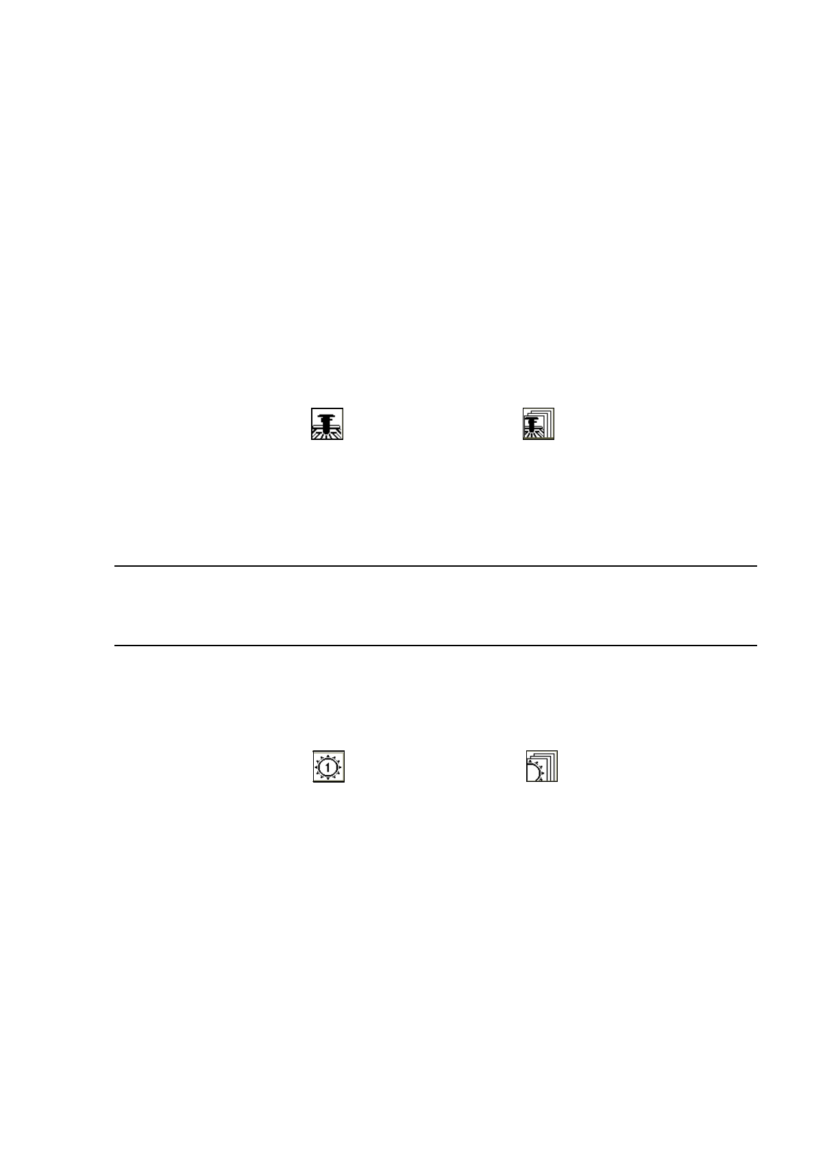
In the main view click on the icon and then (if required) the icon in order to reach the "Gantry
functions" display (see Fig. 0.3.4).
●
Click on the
Head reference run
button.
The reference run will be performed for all axes of the revolver head and the IC head.
●
Following the head reference run, click on the
Gantry reference run
button.
The gantry axes will perform the reference run.
NOTE
The steps described above also apply to gantries 1 and 2 of SIPLACE 80S-20.
The reference run will be performed for the head and gantry axes associated with the gantry selected.
1.4.3 Reference Run of RV Head
Example: Revolver head 1, SIPLACE 80S-20
●
In the main view click on the icon and then (if required) the icon in order to reach the
"RV head functions" display (see Fig. 0.3.5).
●
Click on the Head reference run button.
The reference run will be performed for all axes of the revolver head of gantry 1.
●
If you wish to close the nozzles and move the (center) sleeves to the 0-degree position, click on the
Swivel out segments / close noz. button.