00191021-02 - 第58页
1 General Functions User’s Manual Test P rogram SITEST 1.9 In-/Output F unctions Software Version 403.xx Edition 12/97 1 - 22 ● In the mai n view " SIPLACE 80F 4 " click on the icon and the n (if requi red) the…
User’s Manual Test Program SITEST 1 General Functions
Software Version 403.xx Edition 12/97 1.9 In-/Output Functions
1 - 21
1.9 In-/Output Functions
The functions described in the following serve to selectively interrogate and activate individual bits of the input
and output cards of the SIPLACE machines and the wafflepack changer (only input card).
1.9.1 Inputs SIPLACE 80S-20/80F
4
and Inputs WPC SIPLACE 80F
4
●
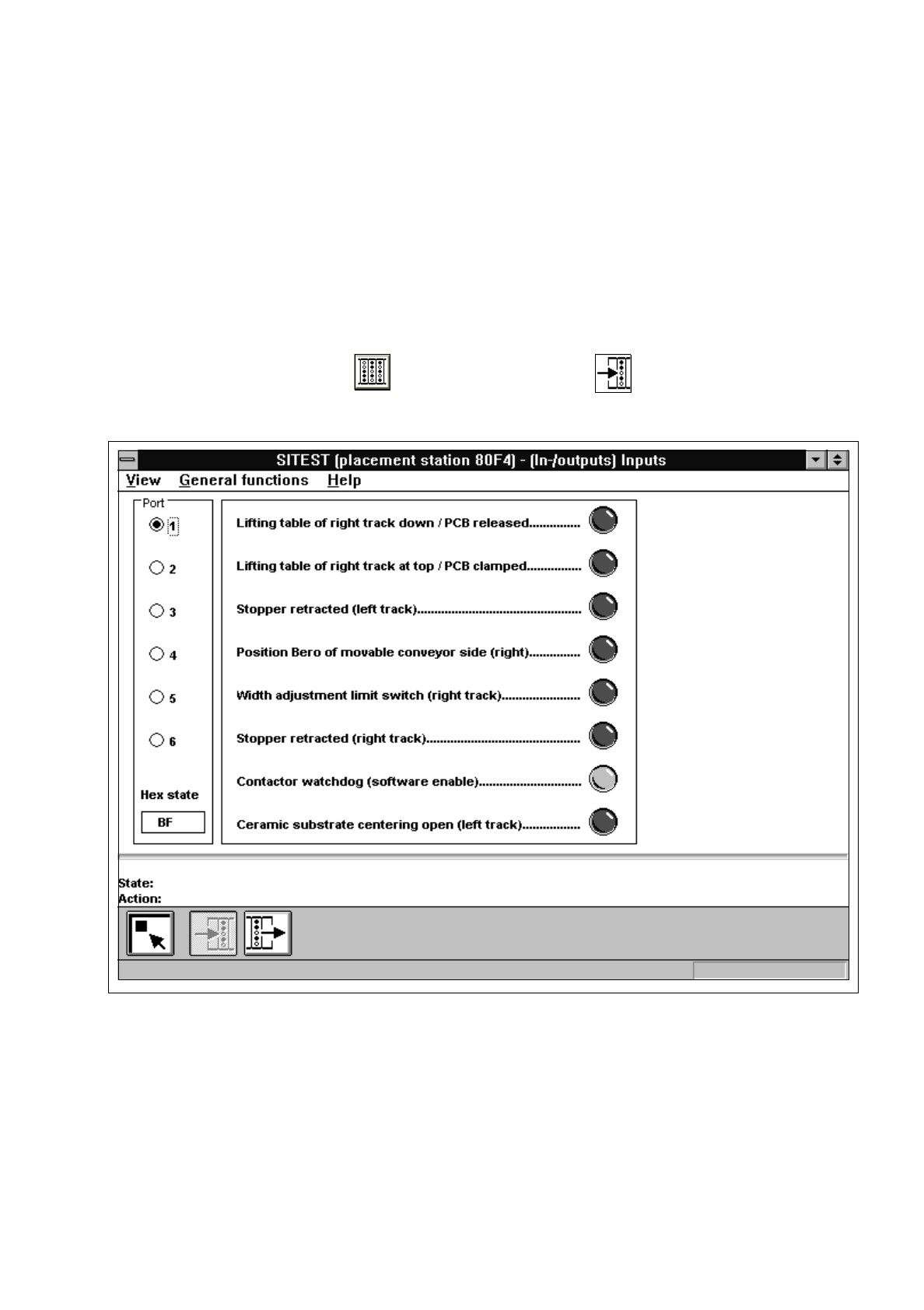
In the main view click on the icon and then (if required) the icon to reach the "Inputs" display
(see Fig. 1.9.1).
Fig. 1.9.1 "Inputs" Display
1 General Functions User’s Manual Test Program SITEST
1.9 In-/Output Functions Software Version 403.xx Edition 12/97
1 - 22
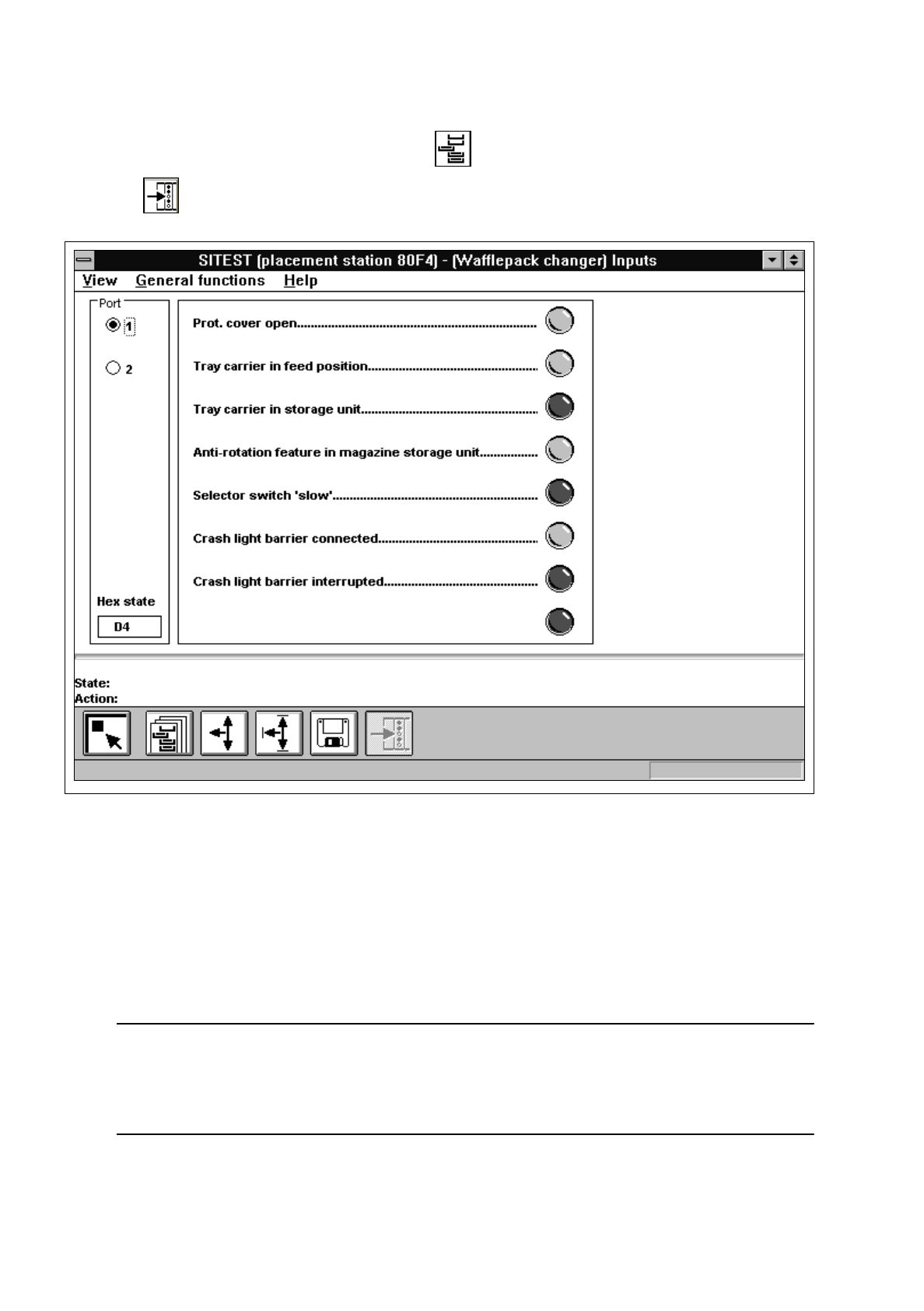
●
In the main view "SIPLACE 80F
4
" click on the icon and then (if required)
the icon to switch to the "WPC / Inputs" display.
Fig. 1.9.2 "WPC / Inputs"
●
If you wish to inform yourself of the state of the bits of a given input port group, activate the correspond-
ing radio button associated with the desired port by clicking on it.
The function of each bit contained in the selected port is displayed next to the "Port" field.
Next to each function the symbol of an LED is displayed whose color changes from gray to red once the
state(s) of the individual bit(s) has (have) been read and displayed in the "Hex state" field.
NOTE
The uppermost LED symbol applies to bit "0", the lowermost to bit "7".
If the LED symbol is displayed in red, the state of the bit is "1" (active).
If the LED symbol is displayed in gray, the state of the bit is "0" (inactive).
User’s Manual Test Program SITEST 1 General Functions
Software Version 403.xx Edition 12/97 1.9 In-/Output Functions
1 - 23
1.9.2 Outputs
●
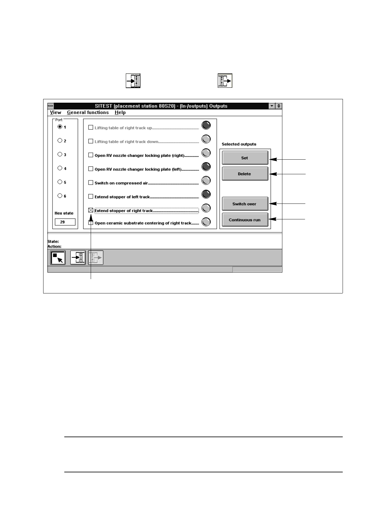
In the "Inputs" display (see Fig. 1.9.1) click on the icon to switch to the "Outputs" display.
Fig. 1.9.3 "Outputs" Display
Legend pertaining to
Fig. 1.9.3
➀
to set the selected bits
➁
to reset the selected bits
➂
to invert the current state
➃
to convert the state of the selected bits in the continuous run
➄
selected bit (output)
➅
LED symbol
●
Activate the appropriate radio button of the port containing the output group you wish to test.
●
Click on the check boxes next to the function descriptions of the outputs you wish to test, or click directly
on the function descriptions.
●
Click on the button indicating the desired function. The selected function will be carried out.
NOTE
The current state of a bit can also be inverted if the corresponding LED symbol is selected by double-
clicking on it.
➀
➁
➂
➃
➄