00191021-02 - 第68页
2 Functions for the A djustment of the Machine User’s Manual Test Program S ITEST 2.1 Axis Functions Software Version 403.xx Edition 12/97 2 - 4 To perfor m the individua l functions, proc eed as follows : ● In the "…
User’s Manual Test Program SITEST 2 Functions for the Adjustment of the Machine
Software Version 403.xx Edition 12/97 2.1 Axis Functions
2 - 3
2.1 Axis Functions
The axis functions are required for the adjustment of the dynamic behavior of the axes.
NOTE
Prior
to the start of the adjustment operations a reference run must be performed for all axes (see
section 1.4).
2.1.1 Gantry Axis Functions
●
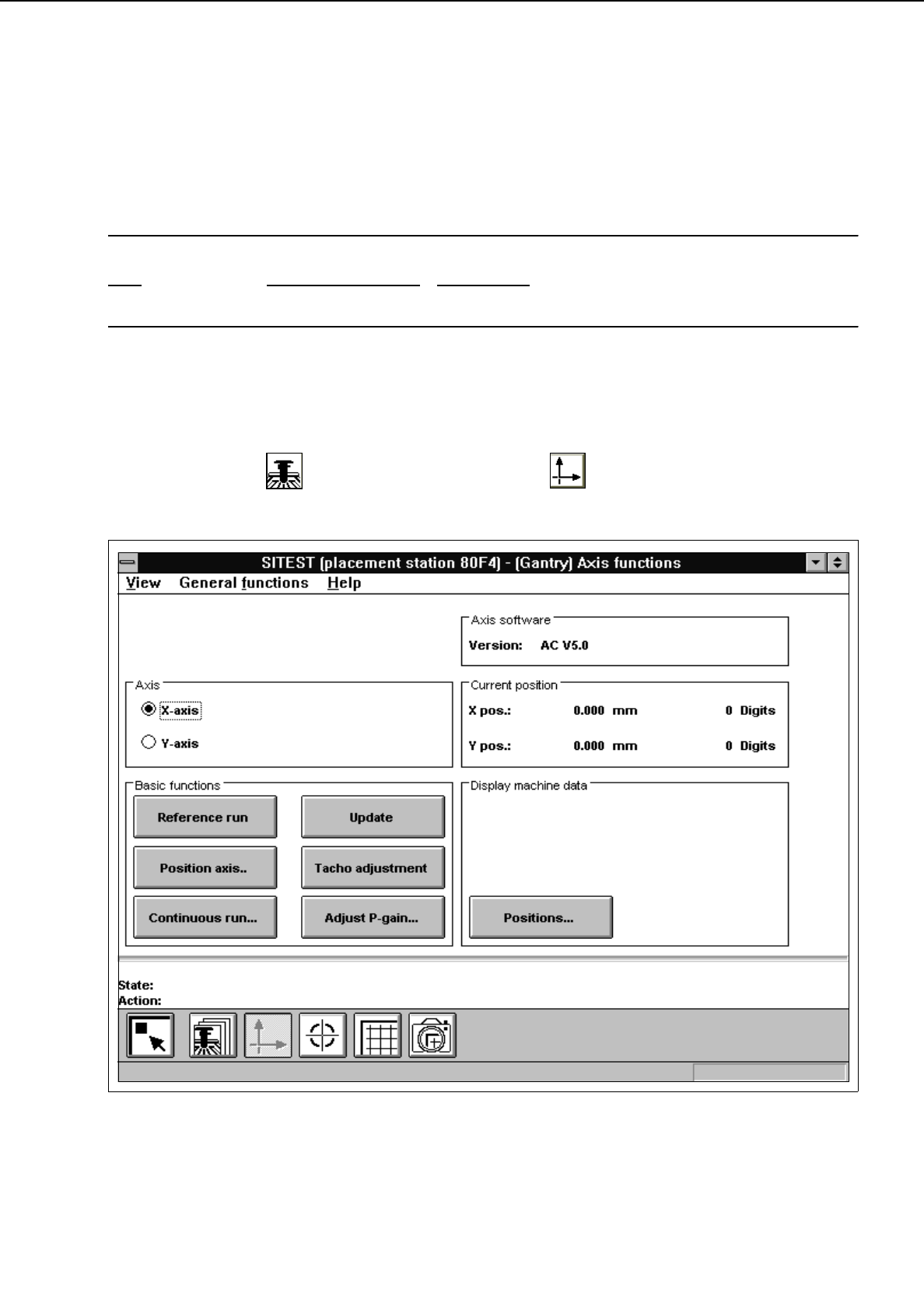
In the "Gantry" display (see Fig. 0.3.4) click on the icon to switch to the "Gantry axis
functions" display.
Fig. 2.1.1 "Gantry axis functions" Display
2 Functions for the Adjustment of the Machine User’s Manual Test Program SITEST
2.1 Axis Functions Software Version 403.xx Edition 12/97
2 - 4
To perform the individual functions, proceed as follows:
●
In the "Axis" field activate the radio button for the axis to be adjusted ("x-axis" or "y-axis")
●
Select the
Reference run
function if the axis has not been referenced yet.
●
To move the axis to a given position in one operation, click on the
Position axis..
button. The setting
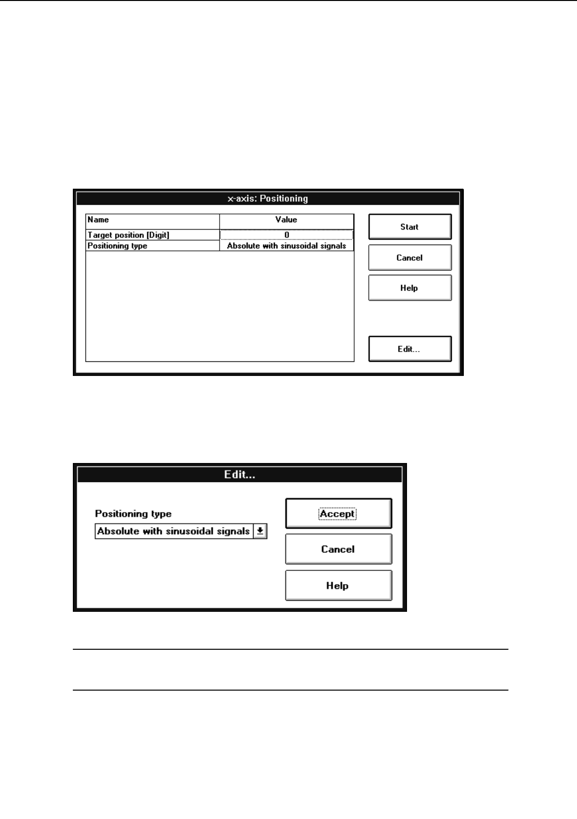
box below opens.
●
Select the
Target position [DIGIT]
line by double-clicking to enter the desired target position. An
input box opens.
●
Enter the target position and confirm your entry by clicking on
Accept
.
●
Select the
Positioning type
line by double-clicking to choose the desired positioning type. The setting
box below opens.
NOTE
In this present software version only one positioning type is available for both the x- and y-axis.
●
Confirm the selected positioning type by clicking on
Accept
.
User’s Manual Test Program SITEST 2 Functions for the Adjustment of the Machine
Software Version 403.xx Edition 12/97 2.1 Axis Functions
2 - 5
●
Click on the
Start
button in the setting box.
The selected axis will move to the target position entered. The position is displayed in the "Current
position" field (see Fig. 2.1.1).
●
Click on the
Update
button to update the display of the position.
●
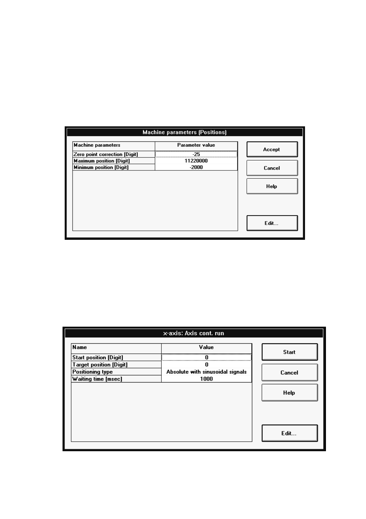
If you wish to change the values for the machine parameters "Zero point cor.value", "Maximum
position" and "Minimum position", click on the
Positions...
button.
The setting box below opens.
●
Select the line containing the parameter you wish to edit by double-clicking.
An input box opens.
●
Change the value as required and confirm your entry by clicking on
Accept
.
●
Once you have completed all desired changes, click on the
Accept
button in the setting box.
●
Select the
Reference run
function to perform a reference run of the active axis.
●
If the selected axis is to be positioned in the continuous run mode, click on the
Continuous run...
button. The setting box below opens.
●
Select each line with the respective parameter you wish to edit by double-clicking.
An input box opens.