00191021-02 - 第71页
User’s Manual Test Program SITEST 2 Functions for t he Adjustment of the Machine Software Version 403.xx Edition 12/97 2.1 Axis Functions 2 - 7 2.1.2 RV Head Axis Functions ● In the " RV head " display (see Fig…
2 Functions for the Adjustment of the Machine User’s Manual Test Program SITEST
2.1 Axis Functions Software Version 403.xx Edition 12/97
2 - 6
●
Change the value as required and confirm your entry by clicking on
Accept
.
●
Once you have completed all desired entries or changes, click on the
Start
button in the setting box.
The axis moves between the start and target positions entered in the continuous run mode.
●
Click on the
Cancel
button in the dialog box to terminate the continuous run.
The completion time of the continuous run is displayed in the dialog box. The label of the "Cancel"
button changes to "OK".
●
Close the dialog box by clicking on
OK
.
●
If the tacho is to be adjusted to the final speed, click on the
Tacho adjustment...
button. The continu-
ous run for the adjustment of the tacho is started. The value measured for the speed deviation is dis-
played in a dialog box.
●
Decrease the value displayed by adjusting the tacho potentiometer on the servo board.
●
After the tacho has been adjusted, click on the
Cancel
button in the dialog box to terminate the contin-
uous run.
●
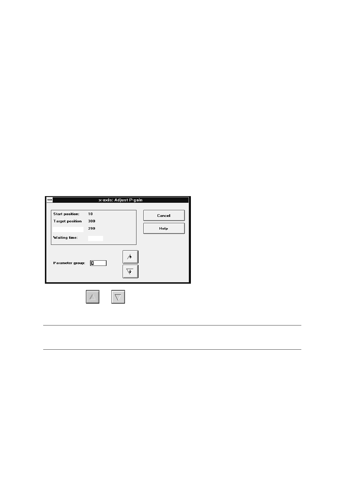
To adjust the P gain, click on the
Adust P-gain...
button.
The continuous run for the adjustment of the P gain is started. The setting box below is displayed.
●
By means of the and icons adjust the desired parameter group entering a value between 1
and 10.
NOTE
Depending on the parameter group entered, the positioning path will be increased or decreased.
●
After the adjustment of the P gain has been completed, click on the
Cancel
button in the setting box to
terminate the continuous run.
1000
Travel path
User’s Manual Test Program SITEST 2 Functions for the Adjustment of the Machine
Software Version 403.xx Edition 12/97 2.1 Axis Functions
2 - 7
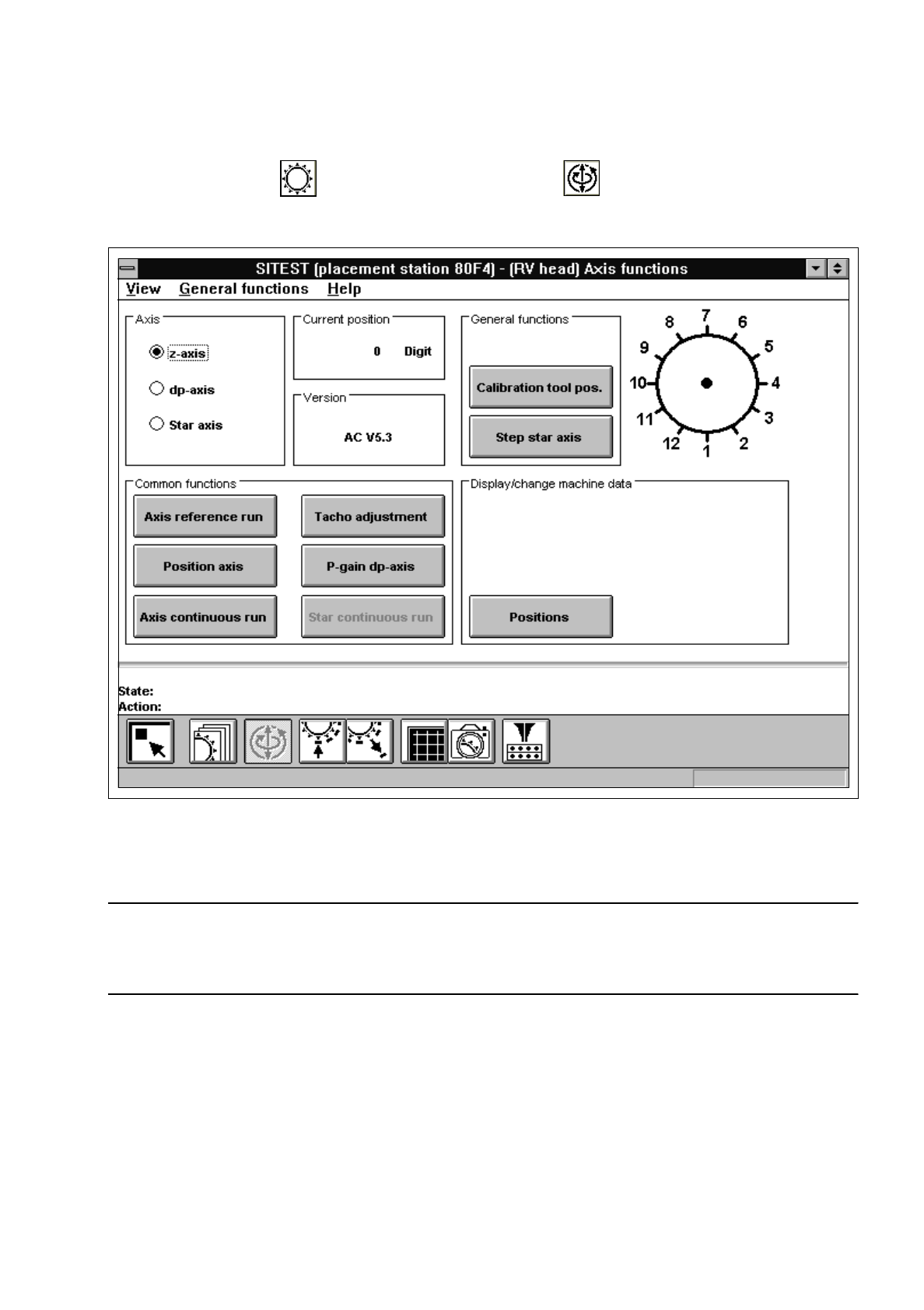
2.1.2 RV Head Axis Functions
●
In the "RV head" display (see Fig. 0.3.5) click on the icon to switch to the "RV head, axis
functions" display.
Fig. 2.1.2 "RV head, axis functions" Display
To perform the individual functions, proceed as follows:
NOTE
Since the layout of some of the setting boxes is identical or similar to that for the gantry axis functions (see
section 2.1.1), these boxes will not be described and displayed again in this section.
●
In the "Axis" field activate the radio button for the axis to be adjusted ("z-axis", "dp-axis" or "Star axis").
●
Select the
Axis reference run
function if the axis has not been referenced yet.

2 Functions for the Adjustment of the Machine User’s Manual Test Program SITEST
2.1 Axis Functions Software Version 403.xx Edition 12/97
2 - 8
NOTE
Prerequisite for the movement of the star (indexing, positioning) is that a head reference run has pre-
viously been performed on the revolver head.
In the event of an axis reference run being performed on the z-axis
after the head reference run, the latter
will be rendered ineffective and all positioning functions for the star will be deactivated. The head refe-
rence run must be repeated in order to be able to execute the aforementioned star functions.
●
To move the axis to a given position in one operation, click on the
Position axis
button. The setting
box for the "Target position" and "Positioning type" opens.
●
All further steps are the same as described in section 2.1.1, page 2 - 4.
NOTE
If the positioning operation for the z-axis has been started, the following information box opens.
●
Click on
OK
to move the z-axis to the normal position following the positioning procedure.
●
If you wish to change the values for the machine parameters "Zero point cor.value", "Maximum
position" and "Minimum position", click on the
Positions...
button.
A setting box opens.
●
All further steps are the same as described in section 2.1.1, page 2 - 5.
●
Select the
Axis reference run
function to perform a reference run of the active axis when the changes
have been completed.
●
If the selected axis is to be positioned in the continuous run mode, click on the
Axis continuous run
button. The setting box for the positioning data opens.
●
All further steps are the same as described in section 2.1.1, page 2 - 5.
●
If the tacho is to be adjusted to the final speed, click on the
Tacho adjustment...
button. The continu-
ous run for the adjustment of the tacho is started.
●
All further steps are the same as described in section 2.1.1, page 2 - 6.