00191021-02 - 第88页
2 Functions for the A djustment of the Machine User’s Manual Test Program S ITEST 2.3 Functions of the Flux Dispenser (S IPLACE 80F4) Software Version 403.xx Edition 12/97 2 - 24 ● Click on t he Rins e button i f you wis…
User’s Manual Test Program SITEST 2 Functions for the Adjustment of the Machine
Software Version 403.xx Edition 12/97 2.3 Functions of the Flux Dispenser (SIPLACE 80F4)
2 - 23
2.3 Functions of the Flux Dispenser (SIPLACE 80F
4
)
●
If you wish to test the flux dispenser functions, click on the icon in the main view "SIPLACE 80F
4
"
(see Fig. 0.3.2) to switch to the "Flux dispenser" display.
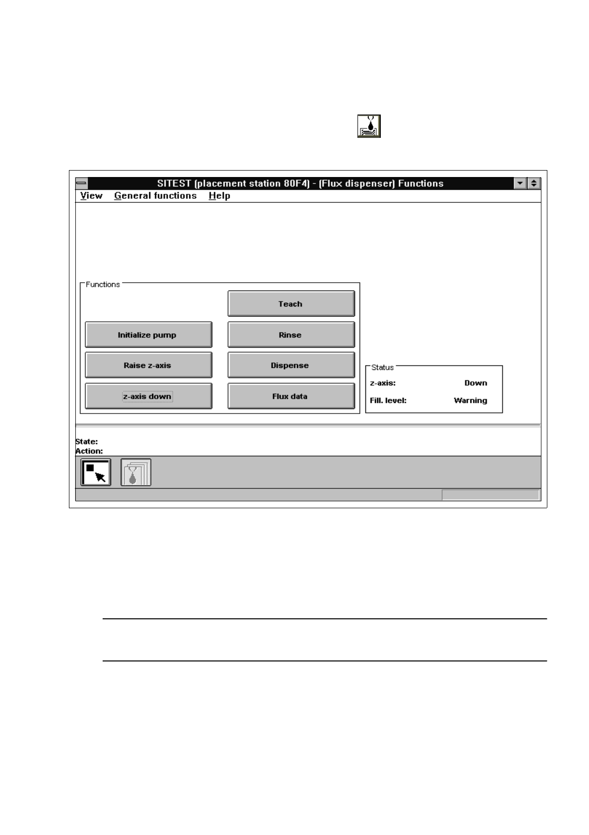
Fig. 2.3.1 "Flux dispenser" Display
●
Click on the
Initialize pump
button to move the stepper motor of the pumps to the pre-defined
position.
●
Click on the
Raise z-axis
or
z-axis down
button to position the z-axis of the flux dispenser.
NOTE
The current state of the z-axis and the flux filling level are displayed in the "Status" field.
●
Click on the Teach button if you wish to move the flux dispenser to any specific position for applying
the flux.
2 Functions for the Adjustment of the Machine User’s Manual Test Program SITEST
2.3 Functions of the Flux Dispenser (SIPLACE 80F4) Software Version 403.xx Edition 12/97
2 - 24
●
Click on the
Rinse
button if you wish to start the rinsing operation for the flux syringe.
The barrel of the flux syringe is filled. Subsequently, the flux dispenser moves over the rinse position
and the barrel’s content is emptied into the rinse container.
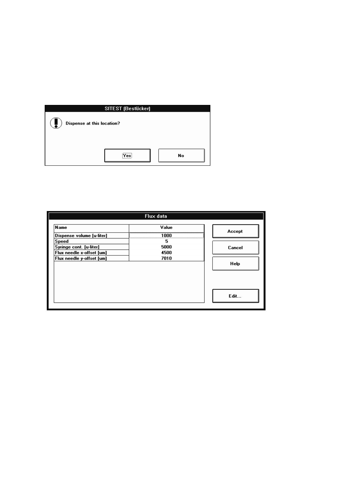
●
Click on the
Dispense
button to deposit the flux.
The dialog box below opens.
●
Click on the
Yes
button if the flux is to be deposited at the current position.
●
Click on the
Flux data
if you wish to display and edit the data, if required. The setting box below
opens.
The following data is displayed and can be edited, if required:
–
Dispense volume [
µ
liter] amount to be dispensed
–
Speed discharge speed of the flux
(a value between 1 and 10 can be entered)
–
Syringe cont. [
µ
liter] content (capacity) of the flux syringe used
–
Flux needle x-offset [
µ
m] distance between flux needle and RV camera in x-direction
–
Flux needle y-offset [
µ
m] distance between flux needle and RV camera in x-direction
●
Select the line containing the value you wish to edit, by double-clicking.
An input box opens.
●
Enter the value and confirm your entry by clicking on
Accept
.
●
Once you have made all the necessary changes, click on the
Accept
button in the setting box.
User’s Manual Test Program SITEST 2 Functions for the Adjustment of the Machine
Software Version 403.xx Edition 12/97 2.4 Head Continuous Run
2 - 25
2.4 Head Continuous Run
This function is designed to perform a complete head test.
NOTE
Prior to starting the continuous run, the respective RV placement head must have been submitted to a refe-
rence run and the gantry must be so positioned that upon lowering the z-axis the (center) sleeve will either
make contact with the conveyor top edge or with a PCB located in the center conveyor.
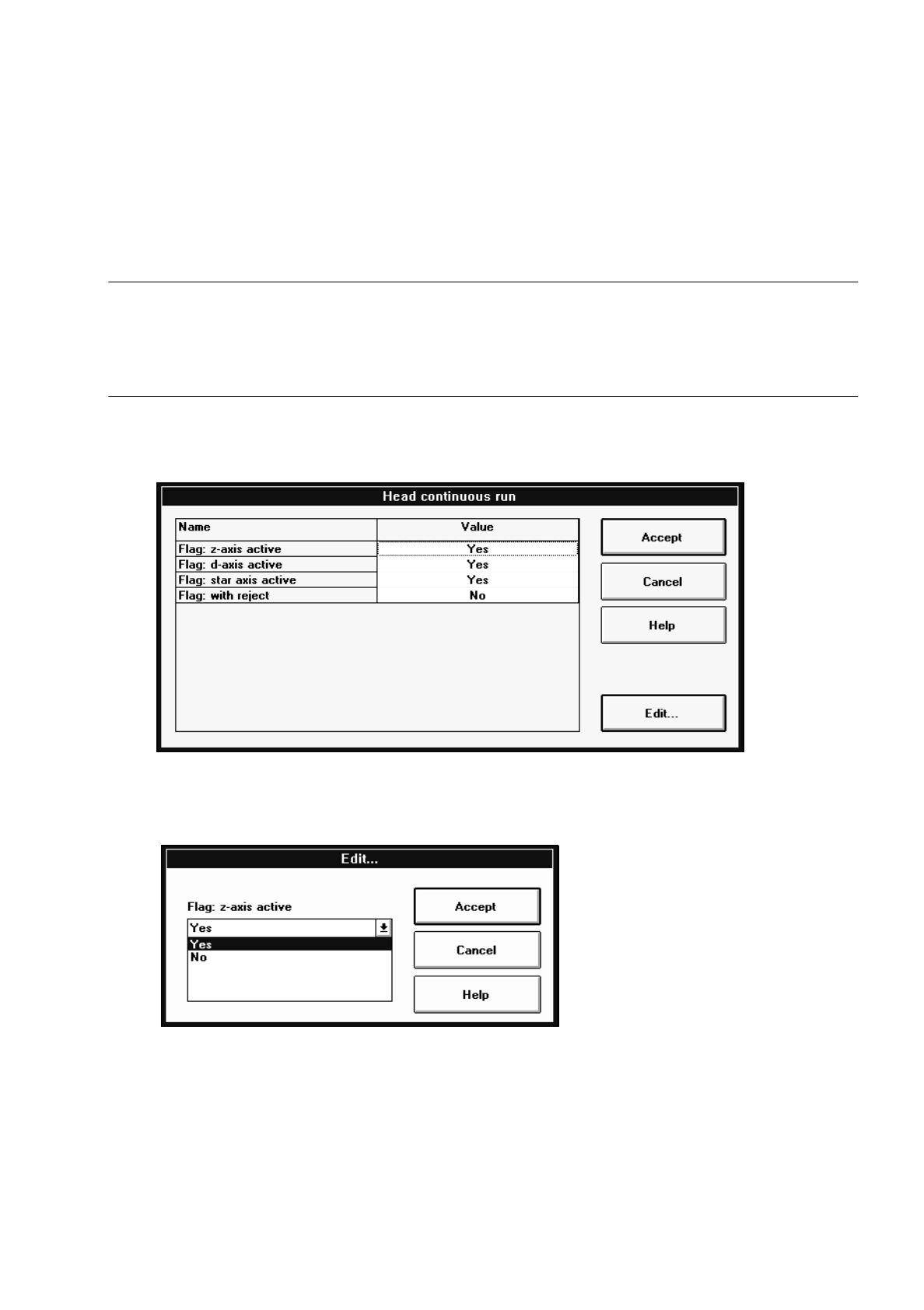
●
If you wish to activate or deactivate head components or options for the continuous run, click on the
Select continuous run options button. The "Head continuous run" setting box opens.
●
Click on the line containing the desired head component or option and then on the Edit... button (or
select the component or option directly by double-clicking on it).
The dialog box below opens.
●
Select the desired option by clicking on it.
●
In each case, click on the Accept button in the dialog box and in the setting box.
●
Click on the Head continuous run button.
The continuous run is started, and a dialog box displaying the start time opens.
●
Click on the Cancel button in the dialog box to terminate the continuous run.
The completion time of the continuous run is displayed in the dialog box. The label of the "Cancel" but-
ton changes to "OK".
●
Close the dialog box by clicking on OK.