YC8_Ope_E.pdf - 第35页
Chapter 1 Par t names and functions Contents 1 4 2.1 Keyboard and mouse 1- 4 5 3. Head assembly 1- 6 3.1 Componen…
iv
About this manual
3. Page layout
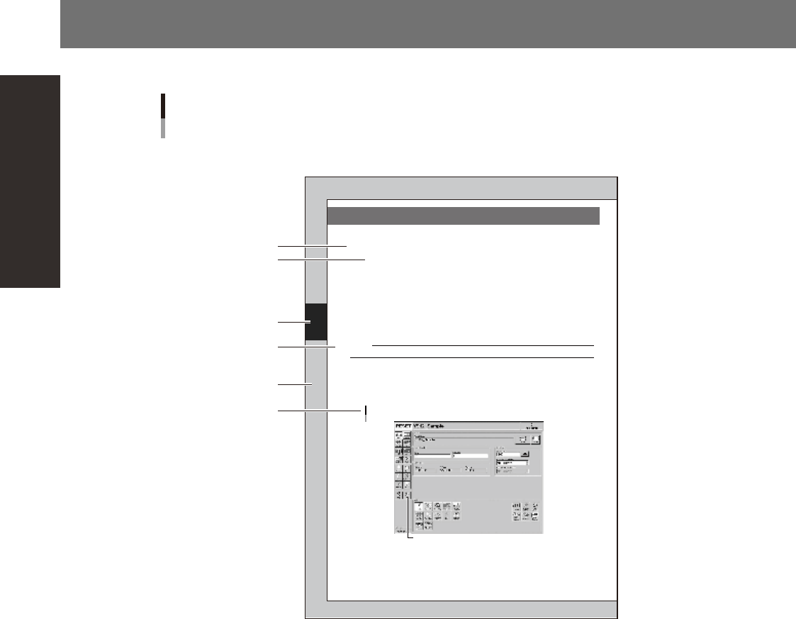
The description below shows a typical page layout used in this manual.
3-8
3
Starting and ending production
2. Ending production and turning power off
Use the following procedure to end board production.
Stop machine operation.
There are four methods for stopping the machine operation.
1. Emergency stop button:
Press this button to trigger emergency stop. Do not use this button in normal operation.
2. [STOP] button (operation panel):
Pressing the [STOP] button stops the machine operation immediately. To resume operation, press the
[STAR T] button on the operation panel.
3. [Cycle Stop] button (operation screen):
Pressing this button stops the machine operation just after components are mounted on the current
board.
4. [Convey-out stop] button (operation screen):
Use this button when you want to end production after completing component mounting on the
boards currently on the conveyor. All boards on the conveyor are carried out after component
mounting, but new boards are not carried in from the upstream side.
CAUTION
Do not press the emergency stop button during operation except in case of emergency.
Reset the operation.
Press the [RESET] button on the operation panel. The machine then returns to the board production
standby status.
Press the [Off] button.
Press the [Off] button in the left button area of the screen.
[Off] button
[Off] button
24306-L6-00
Typical page layout
Step
Chapter number
Chapter title
Substep or
description of step
Figure, picture
or table caption
Note, Caution
or Warning
23001-L0-00
n
Step
This describes the procedure for each operation.
n
Substep or description of step
This provides detailed information on the steps in the procedure.
n
Figure or table caption
This is the title of the figure or table and appears at the upper left.
n
Note, Caution or Warning
These are explained in detail in "Safety instructions".

Chapter 1 Part names and functions
Contents
1
4
2.1 Keyboard and mouse 1-4
5
3. Head assembly 1-6
3.1 Component pick-and-place head 1-6
3.2 Nozzle types 1-7
8
4. Component supply section 1-9
4.1 Supplying components from feeder plates 1-9
0
4.2.1 ATS15 main unit 1-10
4.2.2 Pallet 1-11
5.
Conveyor unit and component recognition system
1-13
6. Axis configuration 1-14
1-1
1
Part names and functions
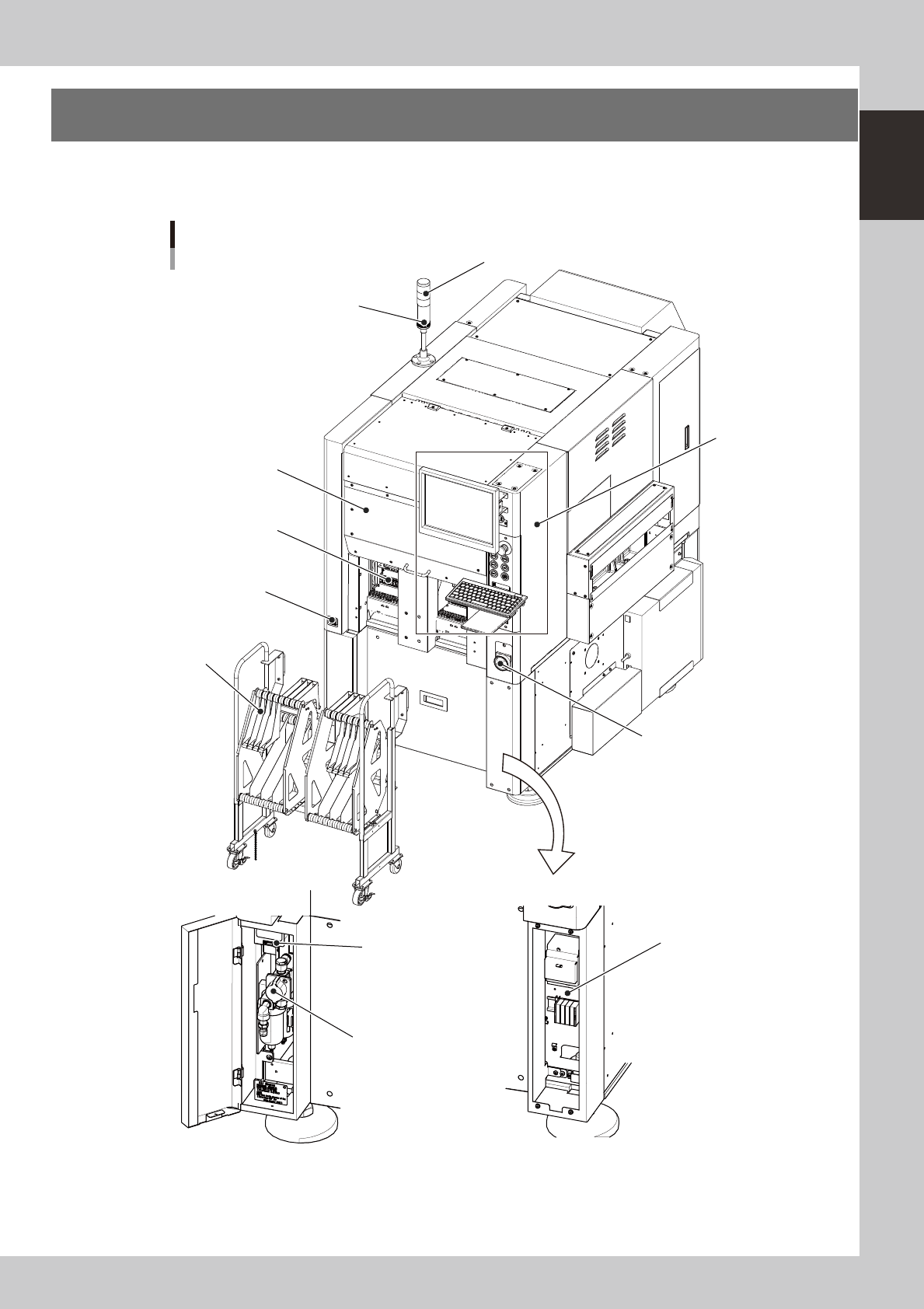
1. Machine main unit
A standard machine has the following configurations after installation is complete. Names and functions of
major parts of the main unit are illustrated below.
Signal light
Operation panel and
data input unit
Power switch
Alarm buzzer
Safety cover
Pressure gauge
Air pressure supply/
shutoff switch
Power connection terminals
Machine main unit
Front view
USB port
Tape reel holder
(option)
Feeder setup section
Behind lower left door Behind lower right cover
23100-N8-00