YC8_Ope_E.pdf - 第49页
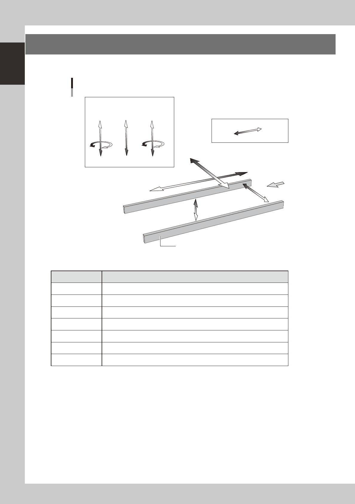
1-14 1 Part names and functions 6. Axis configuration The machine axis configuration and operation are shown in the drawing and table below . Y axis Z2 CZ Z1 X axis W axis PU axis Plus direction Minus direction Board Con…
1-13
1
Part names and functions
5.
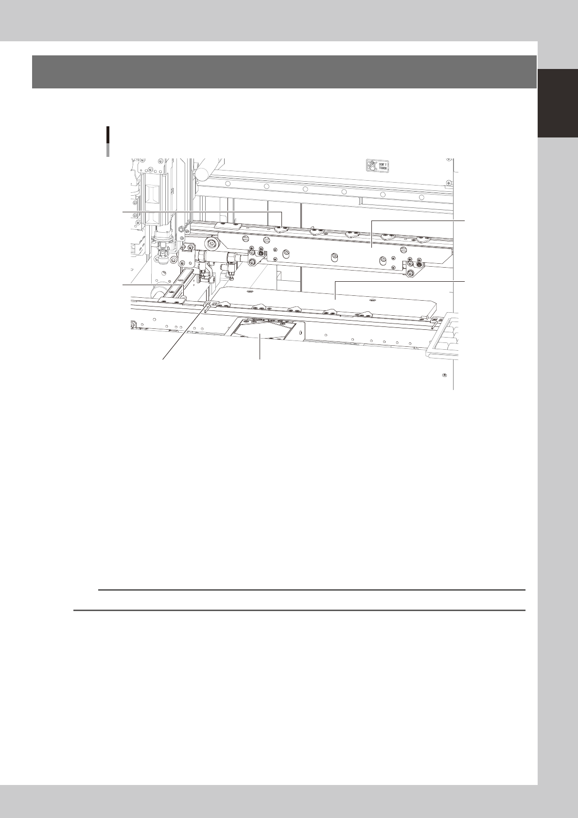
Conveyor unit and component recognition system
The conveyor unit used to clamp a board in mounting position is described below.
Conveyor unit
3
1
5
6
4
2
23112-N8-00
1. Main stopper
When a board is carried in on the conveyor, the main stopper halts travel of the board in the component mounting
position.
2. Push-up plate
The push-up plate clamps the board up against the conveyor rails, with the supporter pins (push-up pins) attached by
magnet on the push-up plate.
3. Board hold plate (movable)
These plates hold the edges of the board from above when the board is clamped in the mounting position.
4. Board edge clamp unit
This unit clamps the board by pushing its edges up against the board hold plates.
5. Board sensor
Board sensors are arranged at the conveyor entrance and exit, "standby position", "board clamp position", etc.
TIP
Push-up pins and standby/exit sensors are optional.
1-14
1
Part names and functions
6. Axis configuration
The machine axis configuration and operation are shown in the drawing and table below.
Y axis
Z2 CZ Z1
X axis
W axis
PU axis
Plus direction
Minus direction
Board
Conveyor rail
R2 axis
R1 axis
Head
Axis configuration
23113-N8-00
n
Function of each axis
Axis Function
X Moves the head assembly in parallel with the board flow on the conveyor.
Y Moves the head assembly perpendicular to the board flow on the conveyor.
Z1, Z2 Moves the component pickup/mount head vertically.
R1, R2 Rotates the nozzle shafts of each head.
CZ Moves the fiducial camera unit vertically.
W Changes the conveyor width.
PU Moves the push-up plate vertically.

Chapter 2 Basic operation
Contents
1
1.1 Canceling emergency stop 2-1
1.2 Clearing an error 2-2
1.3 Typical errors and troubleshooting 2-3
8
8
2.2 Setup screen 2-11
2.3 Unit screen 2-12
3. Starting and stopping the machine 2-17
3.1 Pre-operation check 2-18
3.2 Starting the machine 2-19
3.3 Warming up the machine 2-21
3
3.4.1 Conveyor unit setup flow 2-24
4. Preparing the component supply unit 2-26
4.1 Setting the tape 2-26
4.2 Setting a tape feed pitch 2-31
4.2.1 Setting a pitch from the mounter 2-31
4.2.2 Setting a pitch from an external setup power station 2-33
4.3 Setting the tray components 2-35
4.3.1 Setting the component trays in the pallet 2-35
4.3.2 Setting a pallet in the ATS15 2-36
5. Settings on the mounter side 2-37
5.1 Setting the "Package" parameter. 2-37
1