YC8_Ope_E.pdf - 第84页
2-34 2 asic operation 4 Check the tape feed oper ation. Press the [FEED] button on the feeder body to check that the tape is fed at the correct pitch. TIP • The feed pitch will always be 2 mm each time the [FEED] or [B…
2-33
2
asic operation
4.2.2 Setting a pitch from an external setup power station
The following describes the procedure for setting a tape feed pitch using the external setup power station.
n
NOTE
See the "SS FEEDER" user's manual for details on the external setup power station.
1
Set a feeder on the external setup power station.
Install the feeder on the guide rail at the left end of the external setup power station.
2
Check the tape feed pitch of the feeder.
The tape feed pitch is indicated on the display as shown below.
Checking the tape feed pitch
Display
23214-N8-00
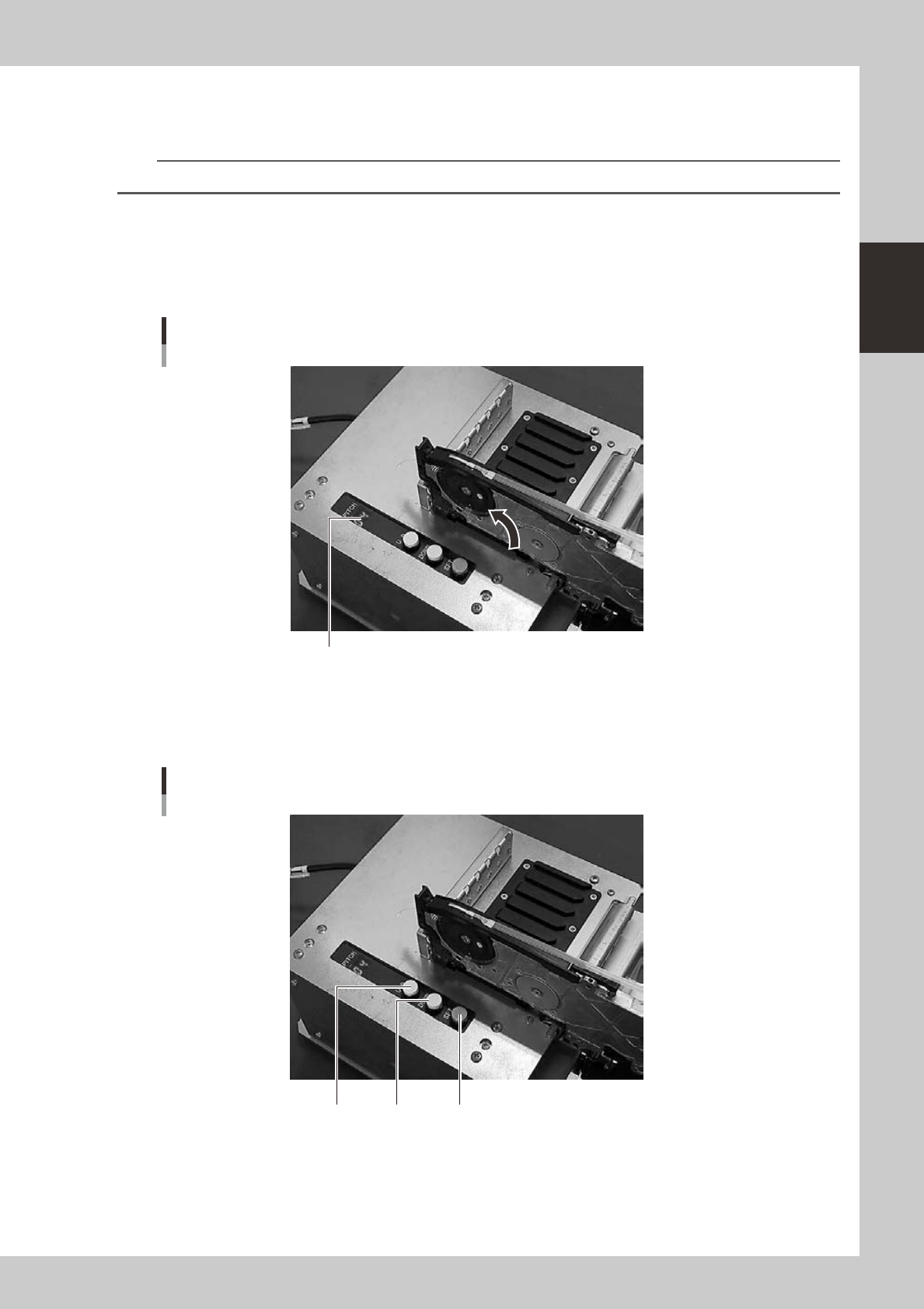
3
Set the tape feed pitch.
Press the [UP] or [DOWN] button to set the feed pitch that matches the components in the feeder, and
then press the [SET] button to determine the setting.
Setting the tape feed pitch
[SET][UP] [DOWN]
23215-N8-00
2-34
2
asic operation
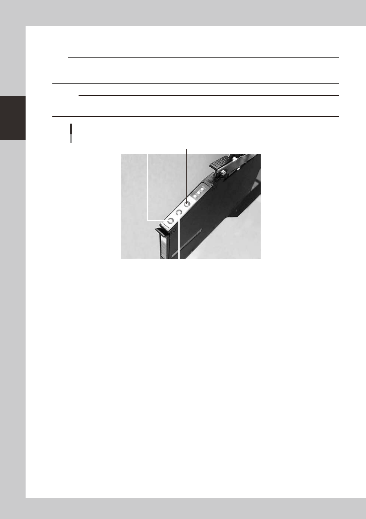
4
Check the tape feed operation.
Press the [FEED] button on the feeder body to check that the tape is fed at the correct pitch.
TIP
• The feed pitch will always be 2 mm each time the [FEED] or [BACK] button on the feeder body is pressed,
regardless of the pitch setting. Holding down either of these buttons feeds the tape continuously.
• Use the [FUNC]+[FEED] buttons to feed the tape at the feed pitch that was set.
c
advance the carrier tape.
Checking the feed pitch
[BACK] button
[FEED] button[FUNC] button
23216-N8-00
2-35
2
asic operation
4.3 Setting the tray components
n
Precautions when handling pallets
Observe the following points when handling the pallets.
• Store the pallets in a clean environment where dust, grime and oil will not adhere.
• Take care not to drop the pallets or apply excessive force or impacts. Do not use a pallet if it is warped or deformed
after having been dropped.
• Avoid hurting yourself on the edges of the pallets.
4.3.1 Setting the component trays in the pallet
Several component trays can be set on one pallet (depending on the size of trays). Set the trays as described
below.
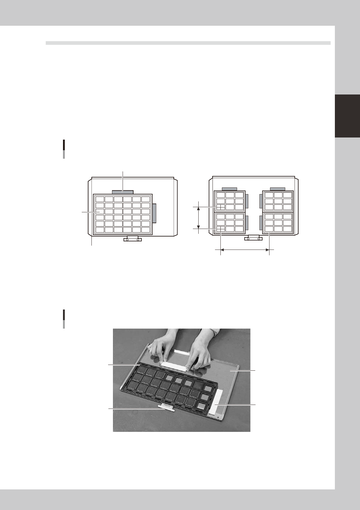
Clamping the component tray
Using one tray
Using several trays
Tray pitch X
Clamping magnet
Tray
Tray pitch Y
Pallet reference position (pallet origin position)
23217-N8-00
1
Remove the tray clamp magnets.
2
Set the component tray on the pallet.
Set so the corner of the component tray is aligned with the pallet reference position (pallet origin
position). After setting the tray, clamp it in place with the magnets.
Clamping the component tray
Pallet pullout piece
Tray clamp magnet
Pallet
Tray
23218-N8-00
3
Check that the component tray is clamped.
Press on the tray to make sure it is securely clamped by the magnet.