YG300_Mainte_E - 第63页
3-25 3 Periodic maintenance items 5 Lo w e r t h e s p l i n e b l o c k . L o w e r t h e s p l i n e b l o c k t o t h e l o w e r e n d . 53 3 4 5 - F 1 -0 0 n NOTE T o make the cleaning work easier , insert air tubes…
3-24
3
Periodic maintenance items
3.2 Cleaning and lubricating the inside of the spline shaft
Dust or grime adhering to the air path of the spline shaft may cause component pickup or mounting errors.
Although depending on the air supply conditions and operating time, the inside of the spline shaft should be
cleaned once every 3 months.
3.2.1 Cleaning the inside of the spline shaft
1
Remove the nozzles from all heads.
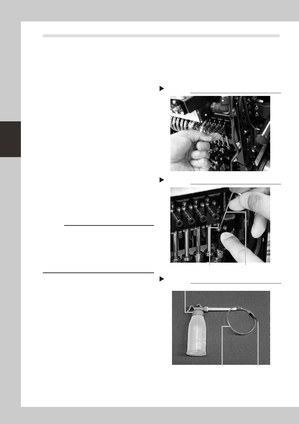
2
Disconnect the air tube from each
spline shaft.
As shown in the photo, disconnect the air
tube inserted into the fitting at the top of
each spline shaft.
53343-F1-00
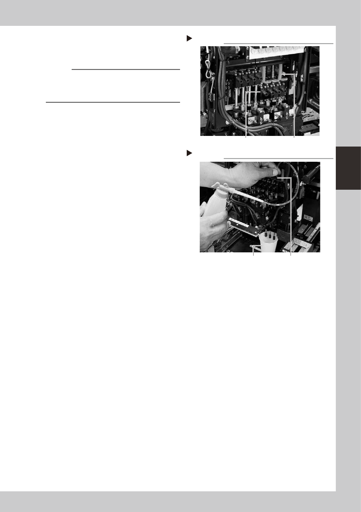
3
Remove the maintenance bolt.
Use the hex wrench to loosen and remove
the maintenance bolt in the center on the
top of each spline block.
53344-F1-00
4
Prepare the cleaning kit (KHW-
M8860-00X).
1. Pour IPA (isopropyl alcohol) into the
container of the cleaning kit.
2. Place a paper cup or tray under the
heads to be cleaned. (This prevents IPA
from flowing out downwards in step 6.)
53348-F1-00
c
CAUTION
The cleaning kit (KHW-M8860-00X) supplied with the
YG300 is exclusive use for the YG300. Do not use this
cleaning kit for other machines. If accidentally used for
other machines, this may clean away the lubricating
grease applied to the packings assembled in the
splines and pistons, resulting in wear of the packings
and causing serious trouble.
Disconnecting the air tubes
Step 2
Removing the maintenance bolt
Maintenance bolt Hex wrench
Step 3
Cleaning kit exclusive for YG300
Step 4
Green cap
Transparent tube
Nozzle
3-25
3
Periodic maintenance items
5
Lower the spline block.
Lower the spline block to the lower end.
53345-F1-00
n
NOTE
To make the cleaning work easier, insert air tubes or
similar items as shown in the photo on the right, so that
the spline block is held in the lower end position. (Air
tube length: 39mm)
6
Clean the inside of each spline
shaft.
1. Insert the nozzle of the cleaning kit into
maintenance hole until the nozzle stops.
2. Pour alcohol (IPA) into the maintenance
hole to clean away dust and grime from
the air path of each spline shaft.
53349-F1-00
7
Blow air into the spline air path.
Using the air blow gun, blow air into the
spline air path from the maintenance hole
(hole from which the maintenance bolt was
removed in step 3).
8
Repeat the above procedure.
Disconnect the air tube and repeat step 6
and then step 7 until the IPA flowing out from
the spline shaft becomes clean.
9
Reinstall the maintenance bolt.
Install the maintenance bolt in the reverse
order of step 3.
0
Reconnect the air tube to each
spline shaft and reattach all
nozzles.
Spline block positioned at lower end
Step 5
Air tube, etc.Spline block
Cleaning the spline shaft
Step 6
Paper cup
Insert the cleaning nozzle.
3-26
3
Periodic maintenance items
3.2.2 Lubricating the slide section and checking the negative pressure
After cleaning the spline shafts, lubricate the buffing parts (slide sections) and check the negative pressure
levels (vacuum levels).
1
Detach the nozzles.
2
Lubricate the buffing parts (slide
sections).
Lubricating oil has been cleaned away by
IPA cleaning, so lubricate the following
parts.
1. Prepare the oil syringe applicator
(KV8-M8870-00X) filled with turbine oil
(VG32).
2. Apply one drop of oil at the elongate
holes at the joint between the nozzle
holder and the spline shaft. (2 locations
for each spline shaft) After applying the
oil, move the nozzle holder up and down
several times.
53346-F1-00
3
Remove excess oil.
Open the [Unit]-[Head] tab screen and press
the [Blow] button to blow air through the
spline shaft.
n
NOTE
A thin coat of oil is enough to lubricate the slide section.
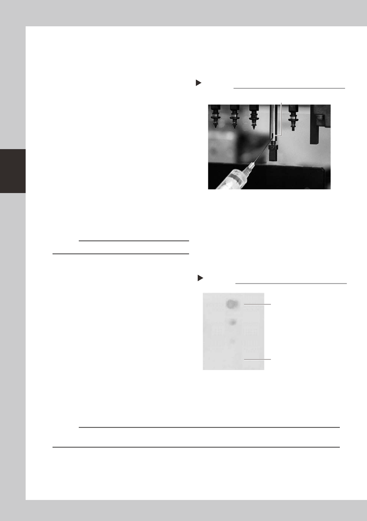
4
Check that the oil was removed.
Blow air through the spline shaft again while
using commercially-available oil blotting
paper, and check for residual oil in the spline
shaft.
53350-F1-00
5
Check the vacuum levels.
On the [Unit]-[Head] tab screen, press the
[Vacuum] button to generate a negative
pressure. Read the "Max" values shown on
the screen and check whether the vacuum
levels are appropriate.
As a general guide, the vacuum level is
normal if the "Max" value is less than 80
when the nozzle is open, and is more than
180 when the nozzle is sealed.
6
Reattach the nozzles.
Attach the nozzles back to the head after
checking one more time that there is no oil
remaining in the nozzles.
n
NOTE
The vacuum level in the spline shaft air path might slightly differ depending on the air source and operating
conditions. Use the above values for reference during maintenance.
Lubrication point
Step 2
Nozzle holder
slide sections
Step 4
Checking for residual oil
Oil blotting paper
Oil may appear after blowing air.
Repeat the air blow until oil no longer
appears.