YG300_Mainte_E - 第65页
Chapter 4 How to replace consumable par ts Contents 1 . R e p l a c i n g t h e n o z z l e l e a f s p r i n g s 4 - 1 2 . R e p l a c i n g t h e a i r j o i n t s 4 - 2 3 . R e p l a c i n g t h e e j e c t o r v a l …
3-26
3
Periodic maintenance items
3.2.2 Lubricating the slide section and checking the negative pressure
After cleaning the spline shafts, lubricate the buffing parts (slide sections) and check the negative pressure
levels (vacuum levels).
1
Detach the nozzles.
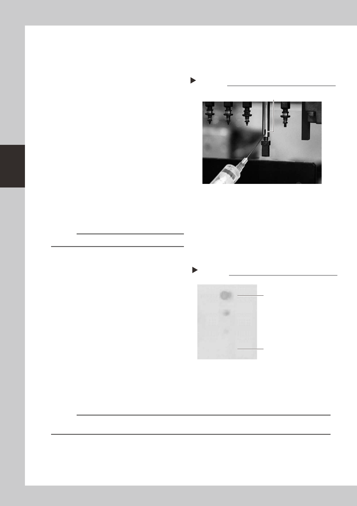
2
Lubricate the buffing parts (slide
sections).
Lubricating oil has been cleaned away by
IPA cleaning, so lubricate the following
parts.
1. Prepare the oil syringe applicator
(KV8-M8870-00X) filled with turbine oil
(VG32).
2. Apply one drop of oil at the elongate
holes at the joint between the nozzle
holder and the spline shaft. (2 locations
for each spline shaft) After applying the
oil, move the nozzle holder up and down
several times.
53346-F1-00
3
Remove excess oil.
Open the [Unit]-[Head] tab screen and press
the [Blow] button to blow air through the
spline shaft.
n
NOTE
A thin coat of oil is enough to lubricate the slide section.
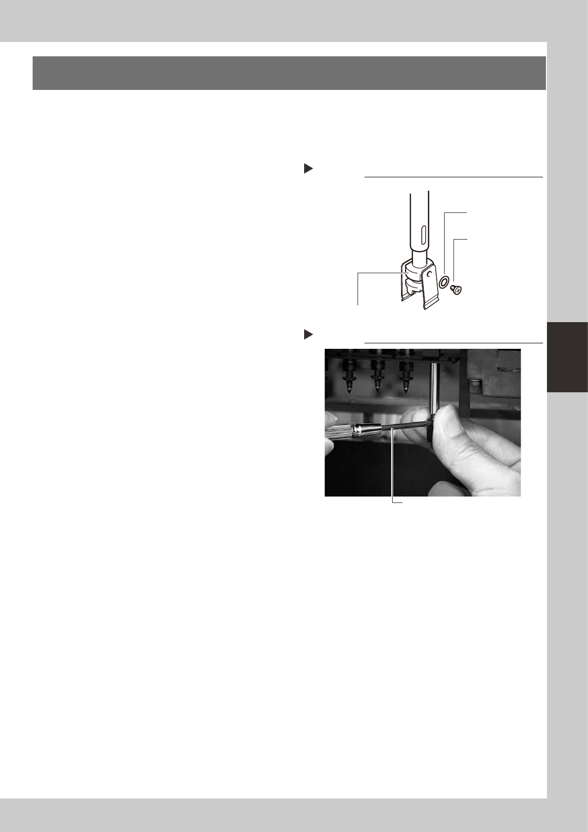
4
Check that the oil was removed.
Blow air through the spline shaft again while
using commercially-available oil blotting
paper, and check for residual oil in the spline
shaft.
53350-F1-00
5
Check the vacuum levels.
On the [Unit]-[Head] tab screen, press the
[Vacuum] button to generate a negative
pressure. Read the "Max" values shown on
the screen and check whether the vacuum
levels are appropriate.
As a general guide, the vacuum level is
normal if the "Max" value is less than 80
when the nozzle is open, and is more than
180 when the nozzle is sealed.
6
Reattach the nozzles.
Attach the nozzles back to the head after
checking one more time that there is no oil
remaining in the nozzles.
n
NOTE
The vacuum level in the spline shaft air path might slightly differ depending on the air source and operating
conditions. Use the above values for reference during maintenance.
Lubrication point
Step 2
Nozzle holder
slide sections
Step 4
Checking for residual oil
Oil blotting paper
Oil may appear after blowing air.
Repeat the air blow until oil no longer
appears.

4-1
4
How to replace consumable parts
1. Replacing the nozzle leaf springs
e
1
Press the emergency stop button.
The machine must be in emergency stop to
ensure safety during work.
2
Remove the nozzle.
Remove the nozzle attached to the leaf
springs to be replaced, by pulling it
downwards by hand.
3
Remove the leaf springs.
Use a Phillips precision screwdriver to loosen
the screws securing the defective leaf
springs and remove the leaf springs from the
nozzle holder while pressing the nozzle shaft
from the back.
53400-F1-00
4
Attach new leaf springs.
While pressing the nozzle shaft from the
back, tighten the screw with the Phillips
precision screwdriver to assemble the leaf
spring. At this point, do not forget to fit the
washer.
53401-F1-00
5
Reattach the nozzle.
6
Check that the nozzle is held
securely.
1. Check that there is no gap between the
leaf springs and nozzle.
2. Attempt detaching and attaching the
nozzle several times to check that there
is no looseness. (see section 2, "Checking
the nozzle leaf springs", in Chapter 2.)
Removing leaf springs
Step 3
Nozzle leaf spring
mounting washer
Nozzle holder
Nozzle leaf spring
mounting screw
Attaching leaf springs
Step 4
Precision Phillips screwdriver