YG300_Mainte_E - 第67页
4-2 4 How to replace consumable parts 2 . R e p l a c i n g t h e a i r j o i n t s e 1 Pr e s s t h e e m e r g e n c y s t o p b u t t o n . T h e m a c h i n e m u s t b e i n e m e r g e n c y s t o p t o e n s u r e…
4-1
4
How to replace consumable parts
1. Replacing the nozzle leaf springs
e
1
Press the emergency stop button.
The machine must be in emergency stop to
ensure safety during work.
2
Remove the nozzle.
Remove the nozzle attached to the leaf
springs to be replaced, by pulling it
downwards by hand.
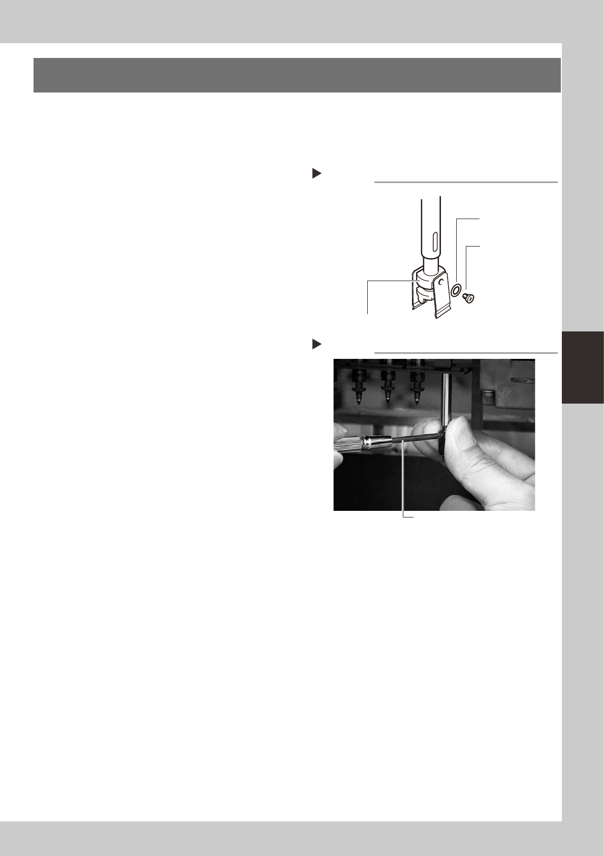
3
Remove the leaf springs.
Use a Phillips precision screwdriver to loosen
the screws securing the defective leaf
springs and remove the leaf springs from the
nozzle holder while pressing the nozzle shaft
from the back.
53400-F1-00
4
Attach new leaf springs.
While pressing the nozzle shaft from the
back, tighten the screw with the Phillips
precision screwdriver to assemble the leaf
spring. At this point, do not forget to fit the
washer.
53401-F1-00
5
Reattach the nozzle.
6
Check that the nozzle is held
securely.
1. Check that there is no gap between the
leaf springs and nozzle.
2. Attempt detaching and attaching the
nozzle several times to check that there
is no looseness. (see section 2, "Checking
the nozzle leaf springs", in Chapter 2.)
Removing leaf springs
Step 3
Nozzle leaf spring
mounting washer
Nozzle holder
Nozzle leaf spring
mounting screw
Attaching leaf springs
Step 4
Precision Phillips screwdriver
4-2
4
How to replace consumable parts
2. Replacing the air joints
e
1
Press the emergency stop button.
The machine must be in emergency stop to
ensure safety during work.
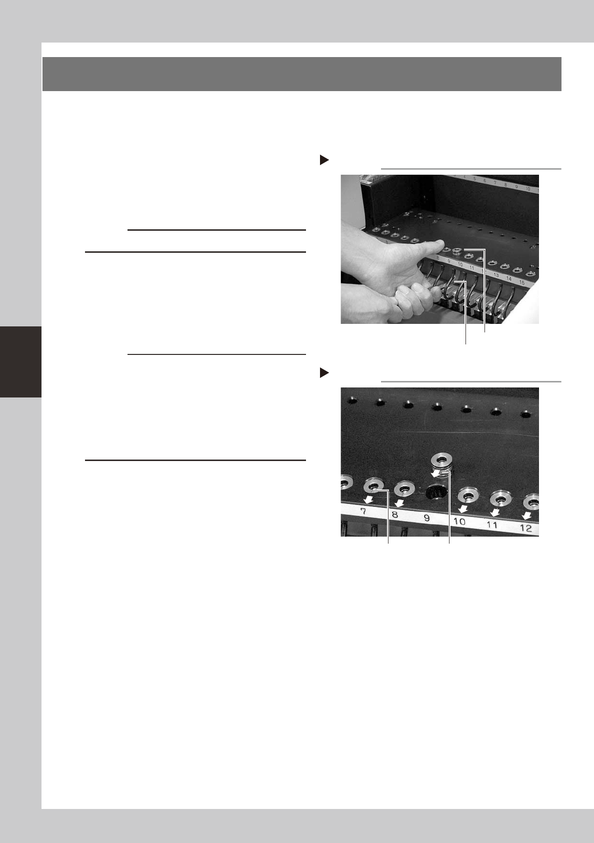
2
Remove the defective air joint.
Insert an M8 hex wrench at the bottom of
the air joint and push it up, then take the air
joint out.
53402-F1-00
c
CAUTION
Be careful not to damage the air hoses.
3
Install a new air joint.
While holding the air joint so the mark
(notch) faces the front side of the machine,
insert it into position from the top of the
feeder plate.
53403-F1-00
c
CAUTION
• Make sure that the mark (notch) faces the front side
of the machine. If the air joint is inserted without
aligning the mark orientation, dust or debris may
penetrate into the air hose.
• Fully insert each air joint into position so that its
surface is lower than the feeder plate surface. Air
joints will slightly rise over time. Reinsert them into
position.
4
Check the operation.
1. Install a feeder at the new air joint
position.
2. Open the [Unit]-[Feeder] tab screen and
check the feeder on/off operation.
Removing the air joint
Step 2
Air joint
Hex wrench
Installing an air joint
Step 3
Mark orientation
Concave mark
4-3
4
How to replace consumable parts
3. Replacing the ejector valves
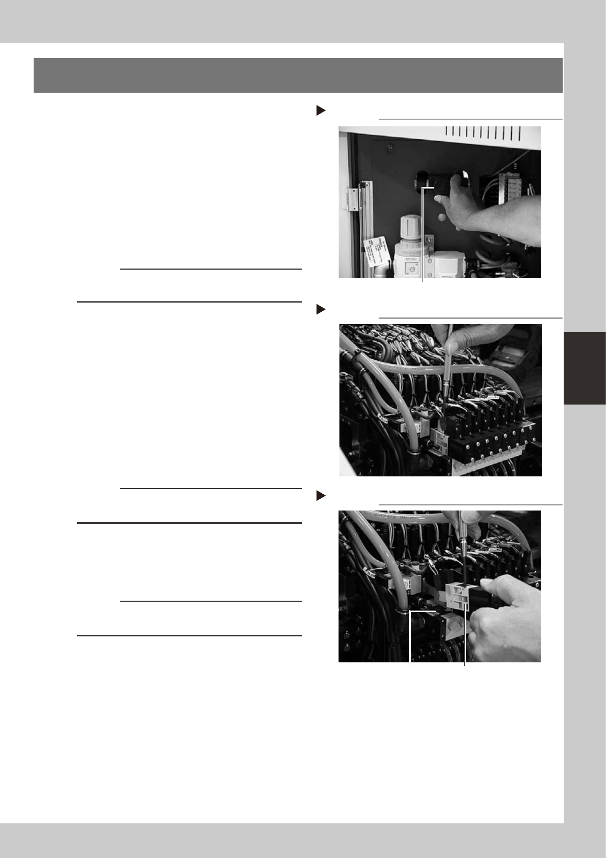
1
Shut off the air supply and turn off
the machine.
Turn the air supply/shutoff switch (located
behind the lower left panel) to the right to
cut off the air supply, quit the application
software (VGOS), and turn off the machine
power switch.
53404-F1-00
2
Unplug the blow valve connector.
Unplug the connector of the blow valve
attached to the ejector valve to be
replaced.
Reference
To replace an ejector valve, the blow valve attached
to that ejector valve must first be removed.
3
Remove the blow valve.
Use the precision Phillips screwdriver to
loosen the two screws securing the blow
valve and then remove the blow valve. You
will see the two screws securing the ejector
valve.
53405-F1-00
4
Remove the ejector valve.
Use the precision Phillips screwdriver to
loosen the two screws securing the ejector
valve and remove the ejector valve.
53406-F1-00
c
CAUTION
Be careful not to drop the gasket fitted to the backside
of the ejector valve.
5
Attach a new ejector valve.
Use the precision Phillips screwdriver to
tighten the two screws to secure the new
ejector valve.
c
CAUTION
Do not forget to fit the gasket in place. Use caution not
to fit the gasket inside-out or to pinch it.
6
Reassemble the valve unit in the
reverse order of the above
procedure.
Reconnect the air hoses and connectors
back to their original positions.
7
Check the operation.
After reassembling the valve unit, supply air
to the machine and turn on the machine
power switch. Then check that the vacuum
levels are normal, using the procedure
described in step 5 of section 3.2.2,
”Lubricating the slide section and checking
the negative pressure", in Chapter 3.
Shutting off the air supply
Step 1
Air supply/shutoff switch
Removing the blow valve
Step 3
Removing the ejector valve
Step 4
Ejector valve
Gasket