00194716-04_AI_Abwurfbehaelter_Abfrage_X-D3_de_en - 第57页
Installation Fitting Sensors for C&P20 and CPP Fitting the Sensors Option Verify Reject Bin Option Abfrage Abwurfbehälter 57 3.1.1.1 Fitting the Nozzle Reject Sensor for C&P20 and CPP ► Fix the sensor S2 to the s…
Installation
Fitting the Sensors Fitting Sensors for C&P20 and CPP
56 Option Verify Reject Bin Option Abfrage Abwurfbehälter
3.1.1 Fitting Sensors for C&P20 and CPP
Overview of sensors for C&P20 and CPP without without stationary cameras
Overview of sensors for CPP with stationary cameras
Installation
Fitting Sensors for C&P20 and CPP Fitting the Sensors
Option Verify Reject Bin Option Abfrage Abwurfbehälter 57
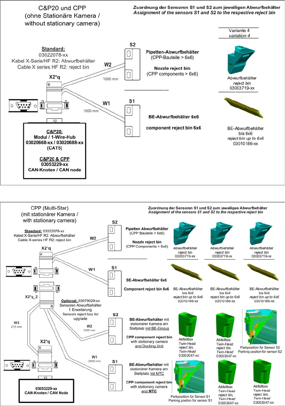
3.1.1.1 Fitting the Nozzle Reject Sensor for C&P20 and CPP
► Fix the sensor S2 to the sensor carrier [03021179-xx] with the 2 plastic screws DIN85-M3x6-PA
[00305381-xx].
► Fix the sensor mount (with sensor) to the nozzle reject bin carrier (2 screws M3x6, DIN912).
CAUTION
Screws
Only use the plastic screws provided to fasten the sensor (DIN85-M3x6-PA [00305381-xx])!
Sensor for the C&P20 nozzle reject bin
1. Sensor mount [03021179-xx]
2. Sensor S2
Installation
Fitting the Sensors Fitting Sensors for C&P20 and CPP
58 Option Verify Reject Bin Option Abfrage Abwurfbehälter
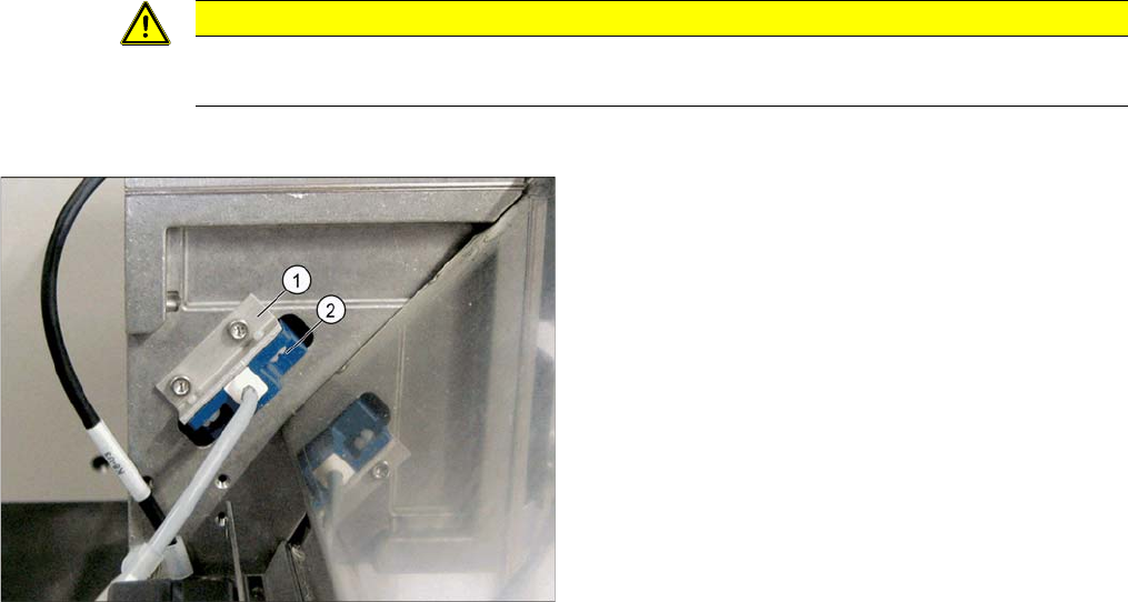
3.1.1.2 Fitting the Reject Bin Sensor 6x6 mm for C&P20 and CPP
► Fix the sensor S1 to the "Sensor-Halteblech LLK" [03009986-xx] with the 2 platic screws (DIN85-
M3x6-PA [00305381-xx]). If the plastic screws are too long, shorten them with a side cutter.
► Now fasten the sensor mount to the empty tape duct with the two filister head screws (RF-SN75-
2.5x6-9.8 [03033796-xx]) but do not tighten the screws yet.
► Switch the machine on.
► Use the slots to set the sensor with the bracket. so that it just reacts when the reject bin is fitted.
CAUTION
Do not tighten the screws
Do not tighten the screws for the sensor mount yet, as the distance between the sensor and
the reject bin 6x6 mm still needs to be set.
Fitting sensor 1 on component reject bin 6x6 mm
1. Component reject bin 6x6 mm
2. Sensor S1
3. Sensor bracket LLK [03009986-xx].
4. Filister head screws
(RF-SN75-2,5x6-9.8 [03033796-xx]
CAUTION
Danger of head crash
The distance between the reject bin and the sensor must be 5 mm. If this is lower, the reject bin
may be positioned too high and could cause a head crash with the C&P20 or CPP head.
► The setting can be checked at the 1 wire hub with an LED.
► When using the CAN node option, observe the display on the user interface.
► The reject bin may not have more than 2 mm upwards play.