00194716-04_AI_Abwurfbehaelter_Abfrage_X-D3_de_en - 第59页
Installation Fitting Sensors for C&P20 and CPP Fitting the Sensors Option Verify Reject Bin Option Abfrage Abwurfbehälter 59 3.1.1.3 Fitting Sensors for CPP with Stationary Camera or MTC If the CPP head is operated i…
Installation
Fitting the Sensors Fitting Sensors for C&P20 and CPP
58 Option Verify Reject Bin Option Abfrage Abwurfbehälter
3.1.1.2 Fitting the Reject Bin Sensor 6x6 mm for C&P20 and CPP
► Fix the sensor S1 to the "Sensor-Halteblech LLK" [03009986-xx] with the 2 platic screws (DIN85-
M3x6-PA [00305381-xx]). If the plastic screws are too long, shorten them with a side cutter.
► Now fasten the sensor mount to the empty tape duct with the two filister head screws (RF-SN75-
2.5x6-9.8 [03033796-xx]) but do not tighten the screws yet.
► Switch the machine on.
► Use the slots to set the sensor with the bracket. so that it just reacts when the reject bin is fitted.
CAUTION
Do not tighten the screws
Do not tighten the screws for the sensor mount yet, as the distance between the sensor and
the reject bin 6x6 mm still needs to be set.
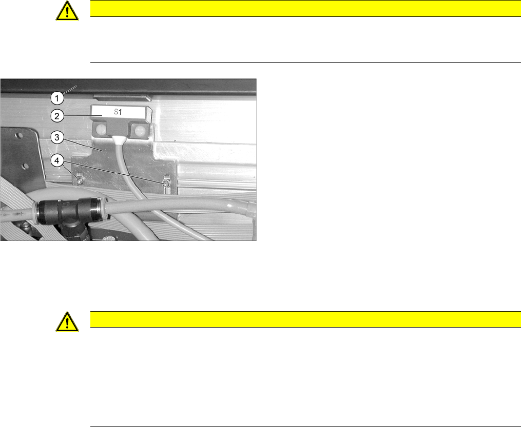
Fitting sensor 1 on component reject bin 6x6 mm
1. Component reject bin 6x6 mm
2. Sensor S1
3. Sensor bracket LLK [03009986-xx].
4. Filister head screws
(RF-SN75-2,5x6-9.8 [03033796-xx]
CAUTION
Danger of head crash
The distance between the reject bin and the sensor must be 5 mm. If this is lower, the reject bin
may be positioned too high and could cause a head crash with the C&P20 or CPP head.
► The setting can be checked at the 1 wire hub with an LED.
► When using the CAN node option, observe the display on the user interface.
► The reject bin may not have more than 2 mm upwards play.
Installation
Fitting Sensors for C&P20 and CPP Fitting the Sensors
Option Verify Reject Bin Option Abfrage Abwurfbehälter 59
3.1.1.3 Fitting Sensors for CPP with Stationary Camera or MTC
If the CPP head is operated in pick&place mode with a stationary camera, you will need additional reject
bins for the larger component spectrum. To check the presence of the additional reject bin, use the "up-
grade sensor cable for reject bin [03079030-xx].
If the stationary camera is retrofitted for the CPP head (X series) [00119782-xx], the reject bin and cable
will already have been supplied. If you convert from a TwinHead to a CPP and still use the stationary
camera with the CPP head, you will need to order this cable.
► Fit the connector X2*q of the "reject bin sensors for upgrade" [03079029-xx] cable between the con-
nectors for the CAN nodes [03035229-xx] and that for the standard sensors [03022078-xx]. (See
also the diagram "Overview of sensors for CPP" in section "3.1.1 Fitting Sensors for C&P20 and
CPP" [ ➙ 56])
► When using a stationary camera at a location with a component feed device, please use the short
cable W2 of the sensor S2.
When using a stationary camera at a location with a MTC, please use the long cable W1 of the sen-
sor S1.
► Remove the reject bin.
► Fix sensor S1 to the bracket under the large component reject bin with the two plastic screws M3x10.
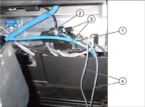
Fitting the upgrade "reject bin sensor cable"
[03079029-xx]
1. X2*q cable for feed device X series: reject bin
[03053229-xx]
2. Cable X series/HF R2: reject bin [03022078-xx]
3. Cable: reject bin sensors for upgrade [03079029-xx]
4. Sensor cable
Installation
Fitting the Sensors Fitting Sensors for C&P20 and CPP
60 Option Verify Reject Bin Option Abfrage Abwurfbehälter
► Reinsert the component reject bin.
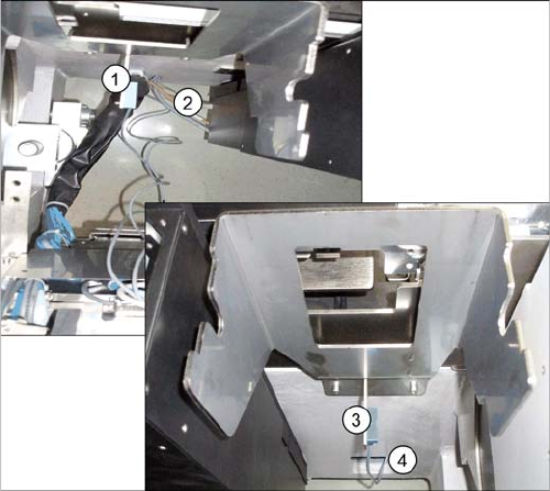
Additional reject bin for CPP with stationary camera
1. Sensor S1 reject bin at location with component feed
device
2. Recesses on machine base at location 1/3
3. Sensor S2 reject bin at location with MTC
4. Recesses on machine base at location 2/4