Composite Material Testing v3.pdf - 第2页
Composit es and S truc tur es T es ting Applica tion Not e She ar T es ting Inst ead of manuf acturing a t esting c omponent that c an be pulled in a uniaxial tes ting fr ame to inves tiga te shear properties, the shear …
Composites and Structures Testing
Application Note
Introduction
Composites are increasingly used across a wide range
of industries to create lighter structures than their metal
equivalents. While steel has a density of 8.1 g/cm
3
, carbon
fibre only has a density of 1.6 g/cm
3
and potentially a higher
yield strength for the same cross section.
The main challenge with most fibre reinforced plastic
composites is that the strength of the structure is typically
not equal in all directions and depend on the direction of
the fibres running through the structure. Sheets of fibres
in one direction may be stacked at various angles, or fibre
tows are woven together to give a specific load bearing
structure or ‘architecture’. This allows the composite to
be stronger in certain directions, maximizing the weight
advantage, but presenting major challenges when testing
the structures to prove that they can stand their
design loads.
The common industry approach to composites is to use
uniaxial tensile testing machines, which were designed
for testing metals. While these machines are commonly
available, the testing that is carried out is limited to
uniaxial loading on an anisotropic material. The stresses on
composite structures are oen peeling or shearing loads,
however conventional testing machines were never built
with this kind of testing in mind. If the structures are tested
in a way that suits the testing machines, then the loads put
on the test samples may be very dierent than the loads
it will see while in service, so the design may be an over or
under estimate. This can lead to heavier structures where
weight reduction is paramount, or a structure that fails in
service due to poor understanding of the performance.
In this application note we explore the benefits of
testing composites and structures using a dedicated
materials tester.
Composites and Structures Testing
Application Note
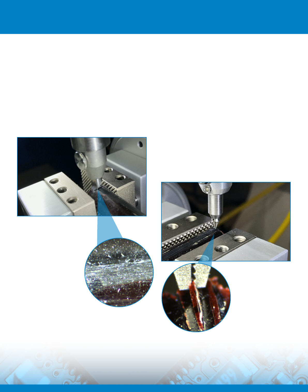
Shear Testing
Instead of manufacturing a testing component that can
be pulled in a uniaxial testing frame to investigate shear
properties, the shear strength can be determined directly
from a component using shear testing. The component
is clamped in a workholder mounted on an XY stage and
sheared against a tool that measures the load. All of
the movement is measured by high precision encoders
within the stage, and further measurements of strain can
be carried out using independent strain gauges that can
interface directly with the materials tester.
Peel Testing
Many components can only be peel tested by
manufacturing materials with two flexible sides that can be
peeled at 90
o
, or one very flexible part that is bent around
180
o
and pulled away from the component. These tests are
diicult to set up and were only developed to make use of
uniaxial machines.
The materials tester can clamp very small features with
its pneumatic jaws and peel material away from the
component at a constant angle of 90
o
by moving the stage
in tandem with the z-axis. This provides a true 90
o
peel test.
Epoxy resins are aected by moisture, which penetrates into
the matrix from the surface. The ability to test fibre-matrix
interactions at a microscale allows for an investigation into
the depth that the composite has been aected, instead of
only testing the bulk properties.
Right: A high magnification
image of the same shear test,
using the onboard trinocular
camera.
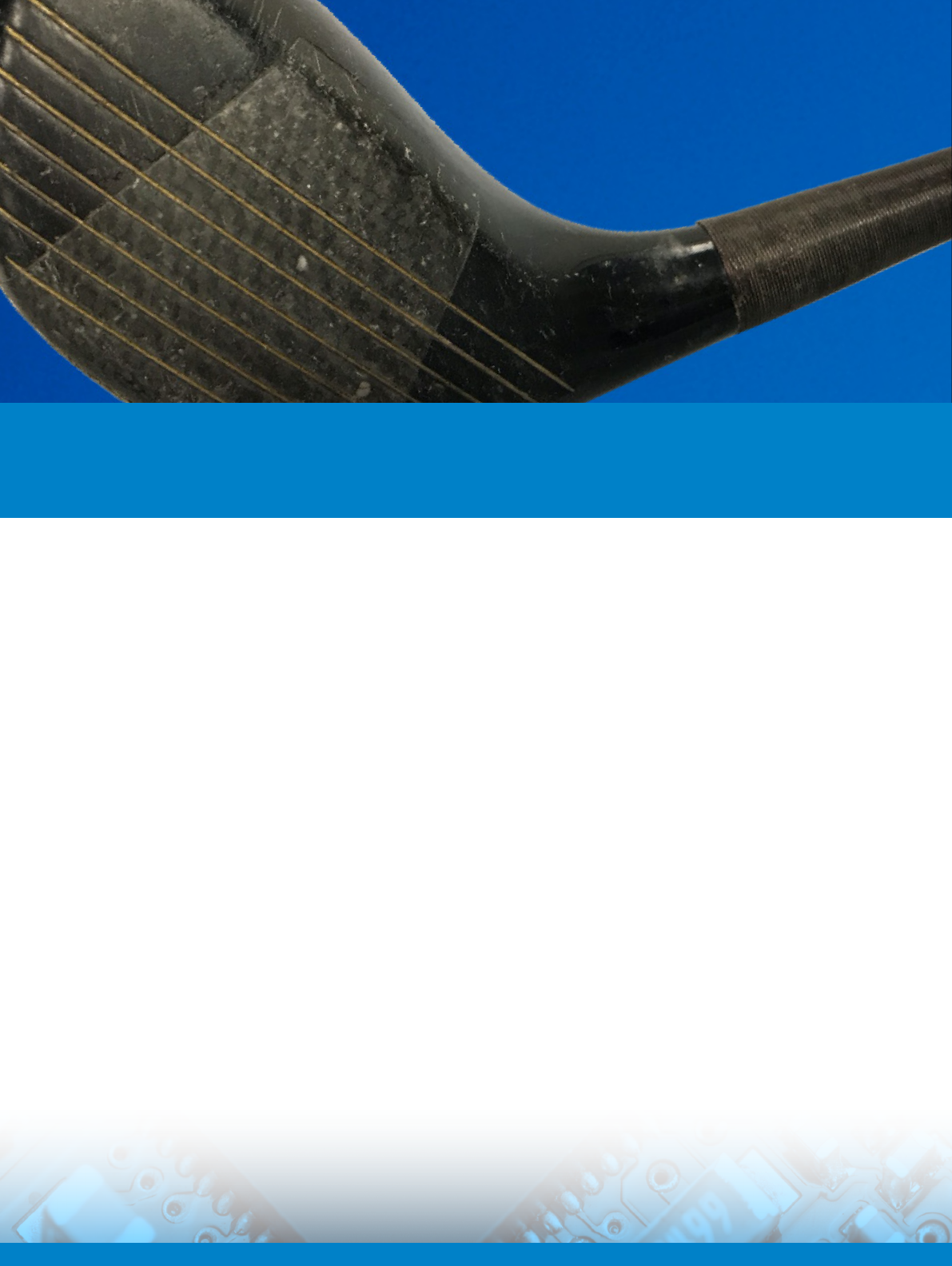
Above: Shear testing of fibres from
a golf club sha to determine the
matrix-fibre interaction.
Le: A composite structure
is held rigidly in place using
high force pneumatic grips
and fibres are peeled from
the surface using precision
tweezer grips.
Bend Testing
While bend testing is more commonly available on
conventional machines, the materials tester can interface
with acoustic emission instruments, to allow cracking prior
to component failure to be detected. This gives a valuable
additional insight.
DAGE Paragon
TM
Materials soware automatically
co-ordinates the materials tester and acoustic emissions
instrument by sending a trigger signal as soon as a user
defined pre-load is achieved.
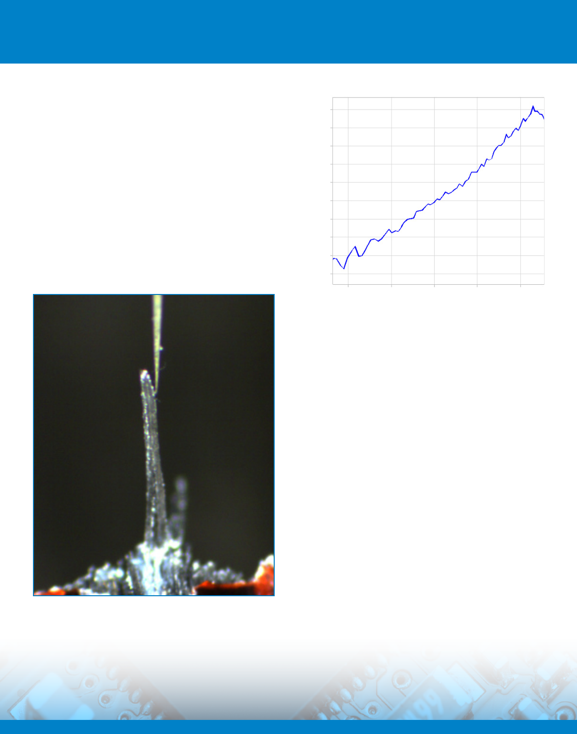
As well as conventional bending, DAGE Prospector
TM
can be
fitted with micro hooks that can be used to li fibre tows so
that the stiness can be measured.
Composites and Structures Testing
Application Note
Liing a 100 micron wide strip of carbon fibre from a
damaged component using a micro hook to investigate
local materials properties.
0.57 0.58 0.59 0.6 0.61
Axis Displacement (mm)
Force (gf)
1.5
1.45
1.4
1.35
1.3
1.25
1.2
1.15
1.1
1.05