cp45电路部分判断.pdf - 第5页
5. ELECTRIC DEVICE Ver. Date CP45 CP45NEO 00 2004/11 O 5-1 5-2. CP(Circuit Protect) Replacement *T o o l s a) +Driver *P a r t a) J3603006A (FAZ-B20-2) : CP#1 b) J3603019A (FAZ-2-D16) : CP#2 c) J9061264A (MK-PW05) : from…
5. ELECTRIC DEVICE
Ver. Date CP45
CP45NEO
00 2004/11 O
5-1
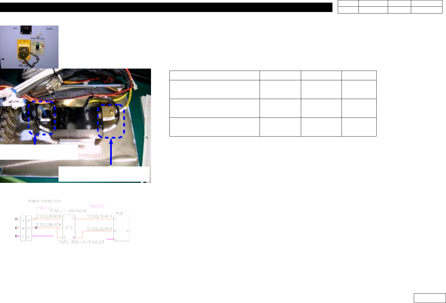
5-1. Replacement Procedure of Curcuit Breaker
*Tools
a) + Driver
*Part
Item
NON-CE CE Remark
CIRCUIT BREAKER
J1202403
(=J3603005A)
J3603008A
MAIN POWER INPUT CABLE
ASS'Y(PW01)
J9080276A J9080310A
MAIN POWER OUTPUT
CABLE ASS'Y(PW02)
J9080277B J9080311B
1) Be Sure to Turn the Main Power OFF when Replacing Circuit Breaker
2) Replace Circuit Breaker(30A)
3) Check the Tag of Cable Terminal of Circuit Breaker Input/Output and Disconnect
* Adjustments after this work
-None
CIRCUIT BREAKER INPUT
:(PW01)
CIRCUIT BREAKER OUTPUT
(PW02)
Fig.5-1-1CIRCUIT BREAKER CONNECTION
5. ELECTRIC DEVICE
Ver. Date CP45
CP45NEO
00 2004/11 O
5-1
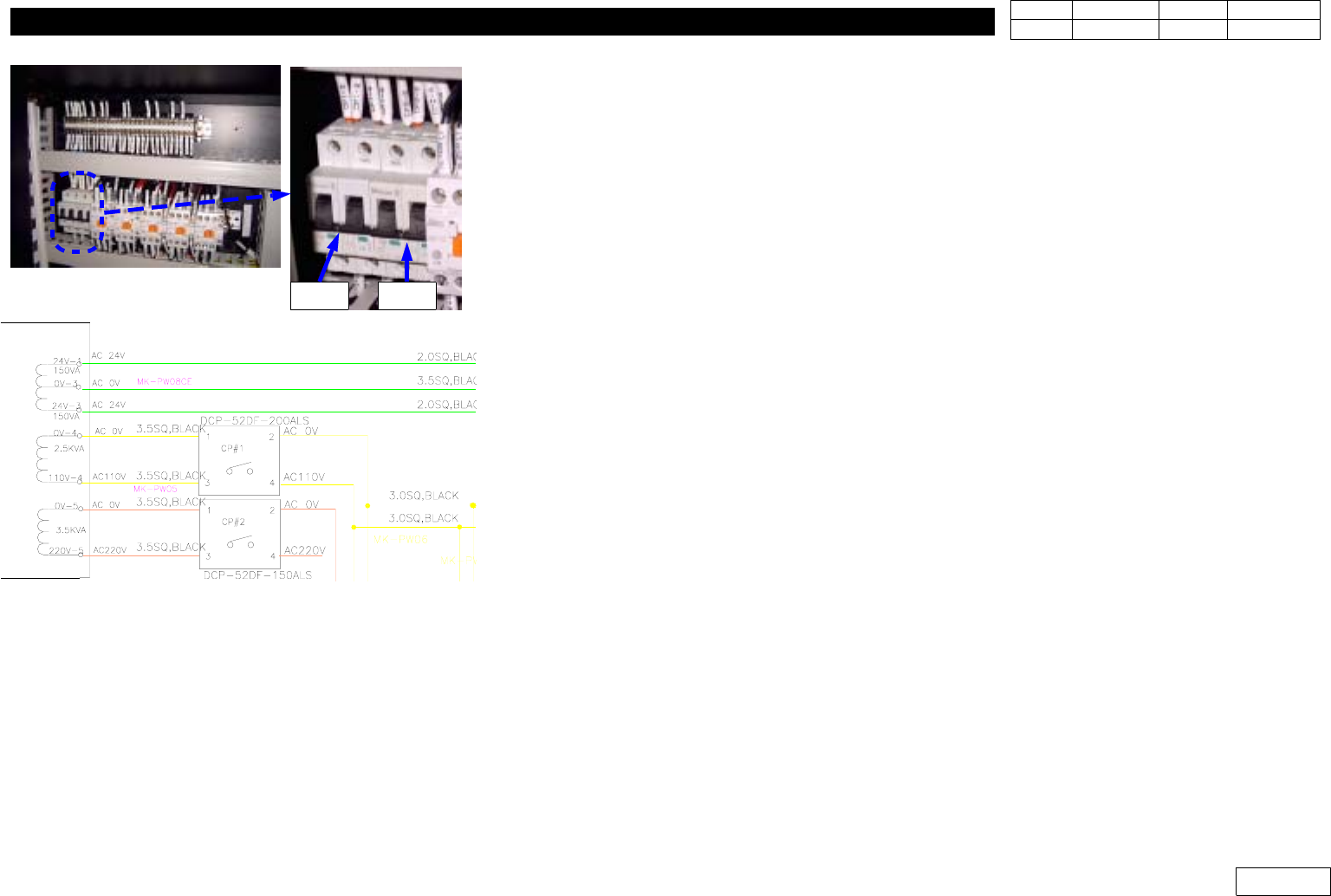
5-2. CP(Circuit Protect) Replacement
*Tools
a) +Driver
*Part
a) J3603006A (FAZ-B20-2) : CP#1
b) J3603019A (FAZ-2-D16) : CP#2
c) J9061264A (MK-PW05) : from Tranfomer to CP#1,#2
d) J9061265B (MK-PW06) : f rom CP#1 to TB3,CR#1-1
e) J9061266B (MK-PW07) : f rom CP#2 to TB1,CR#1-2
1) Be Sure to Turn the Main Power OFF when Replacing Circuit Protect
2) Replace Circuit Protect(Should be the Same Specification)
3) Assemble Main Power Cable to Original Terminal Position
4) CP#1 Protects the Power Supply to PC Rack,
and CP#2 Protects the Power Supply to Motor Driver
* Adjustments after this work
-None
Fig.5-2-1 CP(Curcuit Protect) connection
CP#1 CP#2
5. ELECTRIC DEVICE
Ver. Date CP45
CP45NEO
00 2004/11 O
5-1
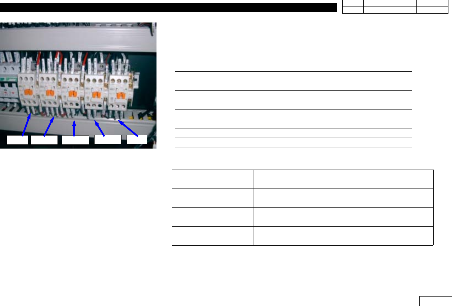
5-3.CR (Circuit Relay) Replacement
*Tools
a) + Driver
*Part
Item
NON-CE CE Remark
Magnetic Contactor J1202401 J35012023A
Transformer power cable ass'y(MK-PW08) J9061267C
Transformer power cable ass'y(MK-PW09) J9061268C
Power cable ass'y(MK-PW10) J9061269C
Power cable ass'y(MK-PW11) J9061270D
Power cable ass'y(MK-PW12) J9061271C
Power cable ass'y(MK-PW13) J9061272B
1) When Disconnecting Cable, be Careful not to Insert Name Tube in Terminal Block
2) Cable Connected to CR is as Followers:
Connection
CABLE title Code Remark
CP#1 -> CR#1-1 Main Power Input Cable Ass'y(MK-PW06) J9061265B
Transfomer -> CR#3 Transformer Power Cable Ass'y(MK-pw08) J9061267C
CR#1-1 -> CR#1-2 Transformer Power Cable Ass'y(MK-pw09) J9061268C
CR#1-2 ->CR#2-1, CR#2-2 Transformer Power Cable Ass'y(MK-pw10) J9061269C
CR#2-1 -> CR#2-2, TB1 Transformer Power Cable Ass'y(MK-pw11) J9061270D
CR#3 -> CR#3, CR#4 Transformer Power Cable Ass'y(MK-pw12) J9061271C
CR#2-2 -> TB1 Transformer Power Cable Ass'y(MK-pw13) J9061272C
* Adjustments after this work
-None
Fig.5-3-1 CR(Curcuit Relay) connection
CR#1 CR#1-2 CR#2-1
CR#2-2 CR#3