GP-551E-03.pdf - 第5页
配置図 O v e r v i e w GP-551E P ARTS LIST ver03 配置図 O v e r v i e w 4 . Y a x i s ( C L S Y ) 1 1 . Z a x i s ( C L S Z ) 9 . O u t c o n v e y o r ( C L Q C ) 2 8 . O u t c o n v e y o r c o v e r ( O p t i o n ) ( C L …

納入後第三者への転売をお考えの際には、必ず事前に弊社へご連絡下さい。
Consult FUJI beforehand if you are considering selling
this equipment to a third party after it has been installed.
パ−ツリストをご利用される前に
1.部品は、図番、コ−ド番号、個数、品名、および規格で発注下さい。
この発注方法以外で発注された場合は発注部品に間違いが生じる恐れがあります。
2.本パ−ツリストは改良のため予告なく変更することがあります。
3.リスト左端の番号が抜けて順番に記載されていない箇所がありますが、これは記載モレや作成途中ではなく
今まで使用していた部品が設計変更により使用されなくなり表から削除されたものです。同時にイラスト内の部品も削除されています。
4.ボルト類,ナット類およびワッシャ類などは種類のみ記載してあります。それぞれの個数は記載せず空欄となっています。
図面原稿 : 1999年 1月
03JE発行 : 1999年 9月
Before Using the Parts List
1. Specify a part number, code number, quantity, part name and rating when ordering parts.
2. This parts manual is subject to change without notice.
3. There are cases where there are no numbers in the left hand column of the parts list. This is not because they were omitted or
the list is incomplete but because the parts to which the numbers applied were eliminated due to a design change.
In such cases the parts have also been removed from the figures.
4. Only the part types are described for nuts, bolts and washers. The quantity column is left blank.
Blueprints created : JAN 1999
03JE released : SEP 1999
5.設計変更した部品(図番の下一桁をカウントアップした部品)は設計変更前の部品と互換です。
しかし、設計変更前の部品は設計変更後の部品と互換であるとは限りません。
例:ABC1231はABC1230と互換であるが、ABC1230がABC1231と互換であるとは限りません。
5. A redesigned part (the last digit of the part number is incremented) is compatible with a part before the redesign.
However,the original part is not always compatible with the revised part,e.i.,ABC1231 is compatible with ABC1230,but
ABC1230 is not always compatible with ABC1231.
TOP

配置図 Overview
GP-551E PARTS LIST ver03
配置図
Overview
4.Y axis(CLSY)
11.Z axis(CLSZ)
9.Out conveyor(CLQC)
28.Out conveyor cover(Option)(CLAK)
7.In conveyor(CLQC)
27.In conveyor cover(Option)(CLAK)
10.Board holder(CLPL)
8.Main conveyor(CLQC)
12.Side clamping(CLPQ)
17.Roller guided main conveyor
(Option)(CLQC)
24.Air device 2(CLPI)
25.Vacuum switch(BSPV)
23.Air device 1(CLPI)
26.Cover(CLAK)
18.Pneumatic circuit diagram 1(CLPI)
19.Pneumatic circuit diagram 2(CLPI)
20.Pneumatic circuit diagram 3(CLPI)
21.Pneumatic circuit diagram 4(CLPI)
22.Pneumatic circuit diagram 5(CLPI)
x22
15.1.Upper cleaner(CLFC)
15.2.Upper cleaner(CLFC)
14.1.Automatic solder-paste dispenser(CLRD)
14.2.Automatic solder-paste dispenser(CLRD)
3.S axis(CLFS)
5.1.Frame holder(CLFB)
5.2.Frame holder(CLFB)
6.Frame holder(For 4000 frame) adapter(CLFB)
13.1.Camera robot(CLGC)
13.2.Camera robot(CLGC)
13.3.Camera robot(CLGC)
1.1.Double squeegee(CLFS)
1.2.Double squeegee(CLFS)
2.1.Hermetic squeegee(CLFS)
2.2.Hermetic squeegee(CLFS)
16.1.Lower cleaner(CLFC)
16.2.Lower cleaner(CLFC)
配置番号は目次番号です
Refer to contents for
the part name of each number
1.1.ダブルスキージ Double squeegee(CLFS)
GP-551E PARTS LIST ver03
1-1
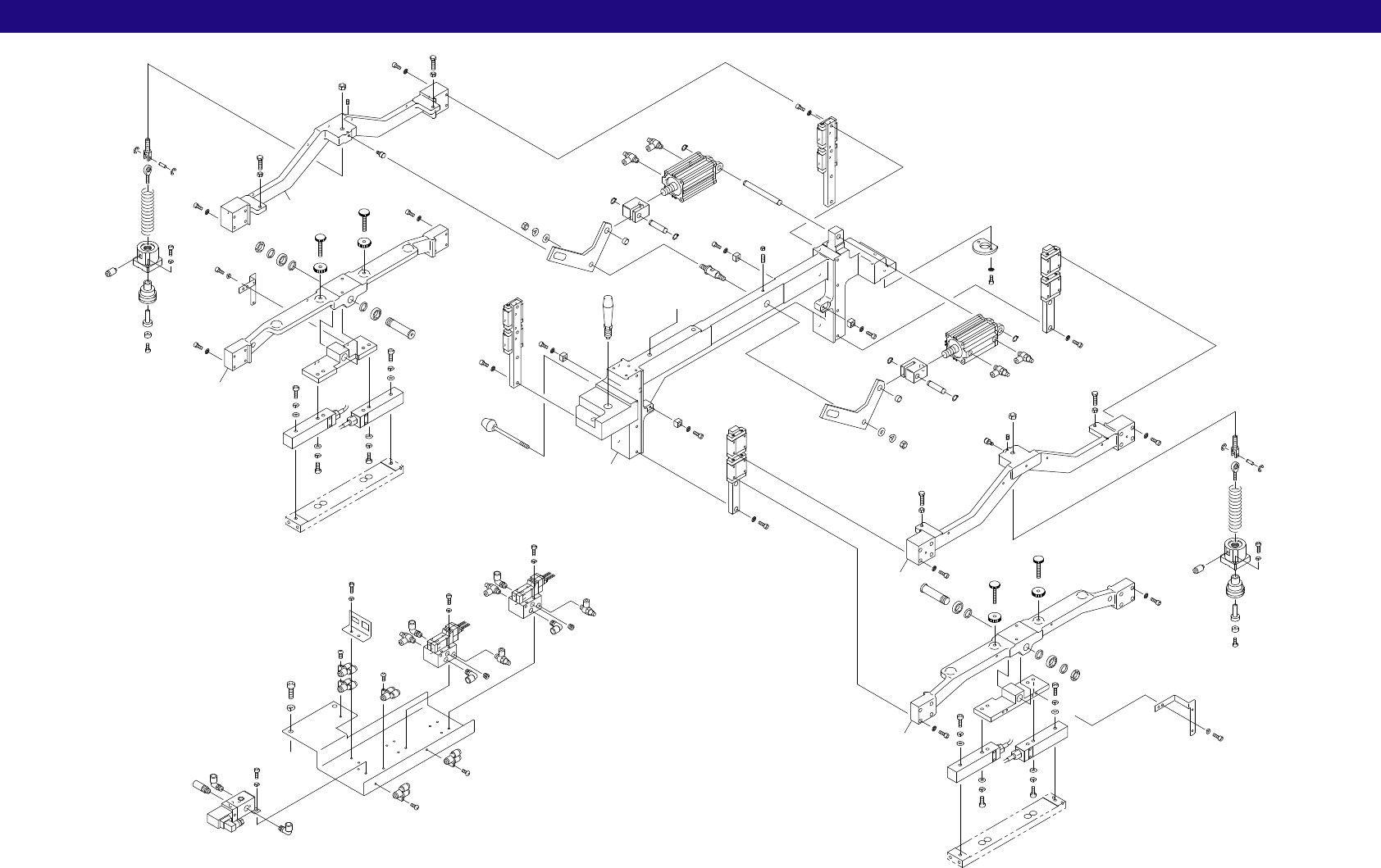
1.1.ダブルスキージ(CLFS)
1.1.Double squeegee(CLFS)
x9
4
3
16
35
40
41
40
41
42
59
42
59
45
45
46
85
100
100
80
80
54
54
55
55
56
57
14
74
89
82
82
82
82
33
34
37
75
38
39
43
47
91
53
53
58
65
33
34
37
75
38
39
43
47
91
53
53
58
65
3
42
59
42
59
85
56
89
82
82
100
100
80
54
54
80
4
16
35
40
41
40
41
45
45
46
55
55
57
13
74
82
82
103
94
76
80
92
76
100
76
100
76
80
94
94
94
94
94
103
94
92
94
76
80
76
80
76
100
76
100
1
82
2
8
84
90
9
101
12
15
15
83
83
15
83
15
83
27
74
28
49
49
50
74
74
51
52
52
81
5
6
7
81
5
6
7
52
52
52
52
61
61
61
61
62
62
63
64
64
64
64
88
87
87
87
67
67
67
67
60
10
82
93
10
82
10
10
82
48
68
68
50
74
62
64
60
62
64
97
93
93
77
85
82
97
93
93
97
77
85
96
96
67
92
77
92
97
A
A