0900766b8171bf63.pdf - 第2页
2 MY(S) Contents Model Number Structure ............................................................................................. 1 Specifications Coil Ratings ........................................................…
1
New Product
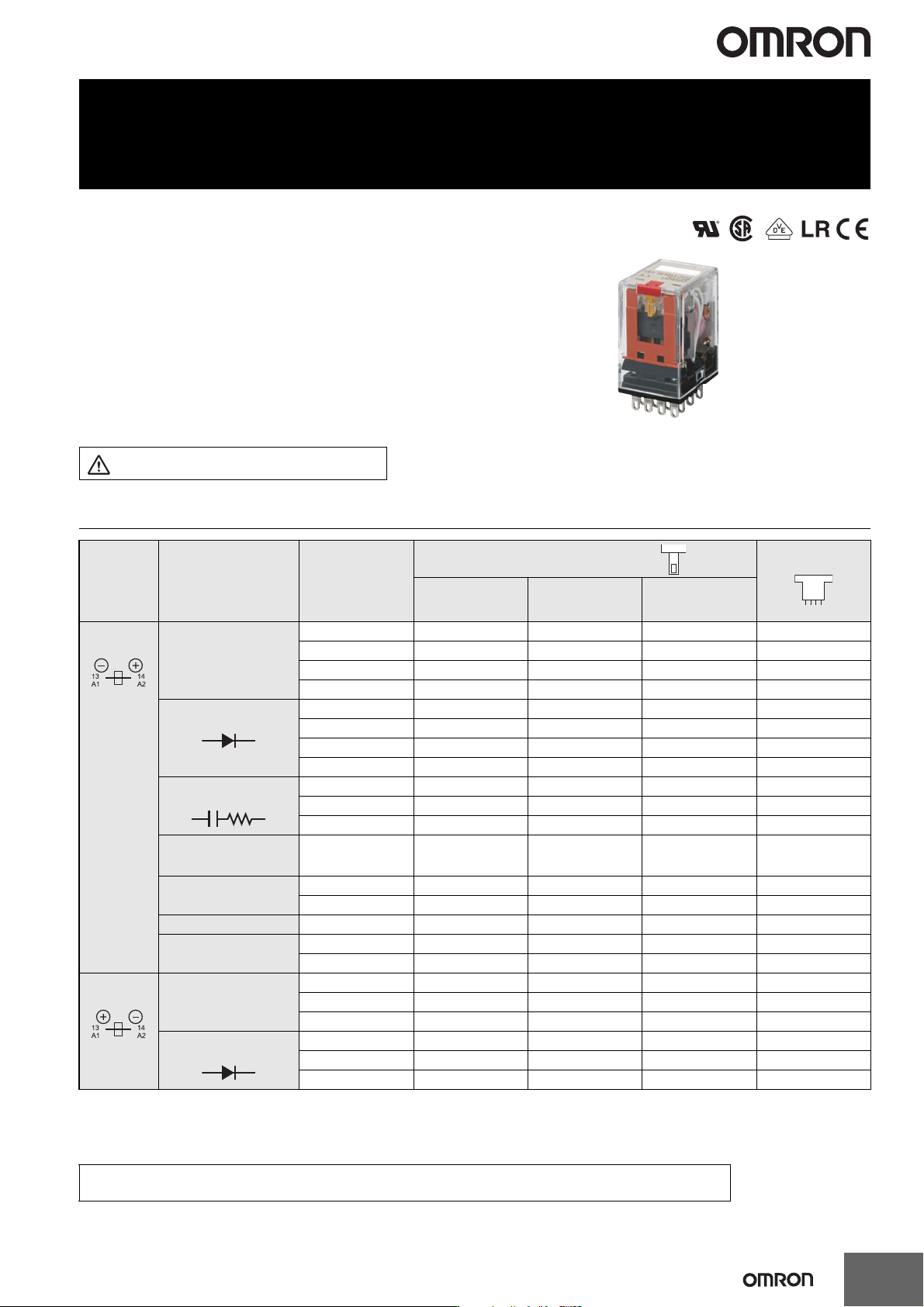
Miniature Power Relays
MY(S)
MY(S) Versatile plug-in Relay
• Reduces wiring work by 60% when combined with the
PYF-PU Push-In Plus Socket
(according to actual OMRON measurements).
• 10 A (DPDT) and 5 A (4PDT)
• Gold-clad contacts (MY4(S))
• Test button (lockable)
• Wide portfolio includes hermetically sealed and
latching types
• 2.6 mm wide pins offer higher conductivity and less
temperature increase
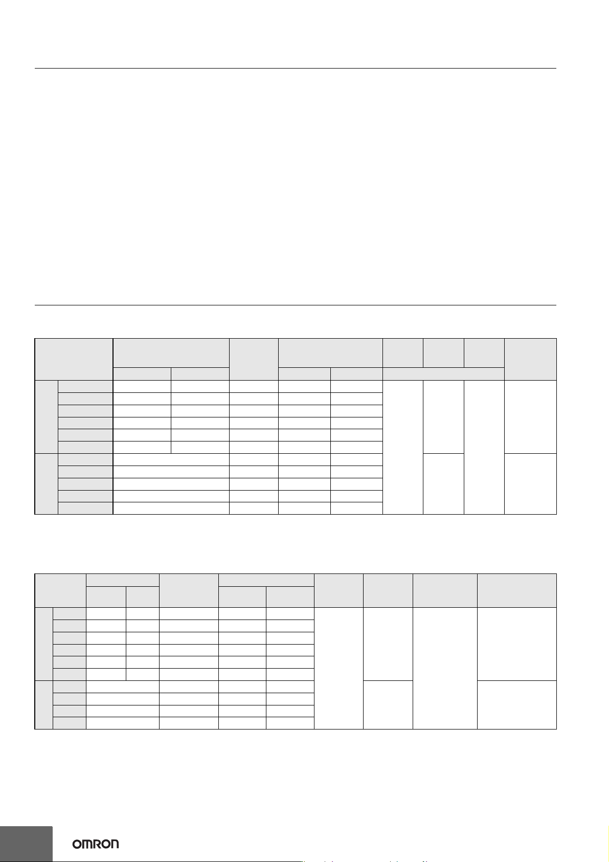
Model Number Structure
* In case of AC coil type relay, please select them from "Type 1" of Coil Polality.
Coil Polarity
(DC case) *
Type Contact form Plug-In socket/solder terminals Flange mounting
With LED indicator With LED Indicator
and Lockable test
button
Without LED
Indicator
Type 1 Standard model DPDT MY2N(S) MY2IN(S) MY2(S) MY2F
DPDT (Bifurcated) MY2ZN --- --- ---
4PDT MY4N(S) MY4IN(S) MY4(S) MY4F
4PDT (Bifurcated) MY4ZN(S) MY4ZIN(S) MY4Z(S) MY4ZF
With Built-in diode
(DC only)
DPDT MY2N-D2(S) MY2IN-D2(S) --- ---
DPDT (Bifurcated) MY2ZN-D2 --- --- ---
4PDT MY4N-D2(S) MY4IN-D2(S) --- ---
4PDT (Bifurcated) MY4ZN-D2(S) MY4ZIN-D2(S) --- ---
With Built-in CR
(AC only)
DPDT MY2N-CR(S) MY2IN-CR(S) --- ---
4PDT MY4N-CR(S) MY4IN-CR(S) --- ---
4PDT (Bifurcated) MY4ZN-CR(S) MY4ZIN-CR(S) --- ---
High reliability contacts 4PDT
(Crossbar
Bifurcated)
--- --- MY4Z-CBG ---
Plastic Sealed 4PDT MYQ4N --- --- ---
4PDT (Bifurcated) --- --- MYQ4Z ---
Lactching (coil latching) DPDT --- --- MY2K-US ---
Hermetic 4PDT --- --- MY4H ---
4PDT (Bifurcated) --- --- MY4ZH ---
Type 2 Standard model DPDT MY2N1(S) MY2IN1(S) --- ---
4PDT MY4N1(S) MY4IN1(S) --- ---
4PDT (Bifurcated) MY4ZN1(S) MY4ZIN1(S) --- ---
With Built-in diode
(DC only)
DPDT MY2N1-D2(S) MY2IN1-D2(S) --- ---
4PDT MY4N1-D2(S) MY4IN1-D2(S) --- ---
4PDT (Bifurcated) MY4ZN1-D2(S) MY4ZIN1-D2(S) --- ---
Refer to Connection Socket and Mounting Bracket Selection Table on page 25 in Options for information on the
possible combinations of Models with Plug-in Terminals and Sockets.
The compliant standards depend on the model.
For details, refer to information provided for individual models.
Refer to the Common Relay Precautions and
Safety Precautions on page 34.
2
MY(S)
Contents
Model Number Structure............................................................................................. 1
Specifications
Coil Ratings ............................................................................................................ 2
MY2(S)/MY4(S)/MY4Z(S).............................................................................................. 3
Engineering Data......................................................................................................... 6
Detailed Information on Models Certified for Safety Standards, MY2(S)/MY4(S)/MY4Z(S)
......... 8
Models Other Than MY(S) Models
MY2ZN ..................................................................................................................... 9
MY@F..................................................................................................................... 11
Detailed Information on Models Certified for Safety Standards, MY2ZN and MY
@
F
.......... 14
MY4Z-CBG ............................................................................................................ 15
MYQ4 ..................................................................................................................... 17
MY2K ..................................................................................................................... 19
MY4(Z)H................................................................................................................. 21
Socket for MY............................................................................................................. 23
Options.................................................................................................................. 25
Safety Precautions .................................................................................................... 34
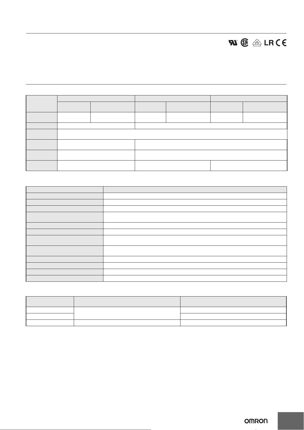
Specifications
Coil Ratings
MY(S)
Note: 1. The rated current and coil resistance are measured at a coil temperature of 23°C with tolerances of +15%/–20% for rated currents and ±15% for DC coil
resistance.
2. Performance characteristic data are measured at a coil temperature of 23°C.
3. AC coil resistance and impedance are provided as reference values (at 60 Hz).
4. Power consumption drop was measured for the above data. When driving transistors, check leakage current and connect a bleeder resistor if required.
MY2ZN, MY@F, MY4(Z)H
Note: 1. The rated current and coil resistance are measured at a coil temperature of 23°C with tolerances of +15%/−20% for the AC rated current and ±15% for the
DC coil resistance.
2. The AC coil resistance and inductance values are reference values only (at 60 Hz).
3. Operating characteristics were measured at a coil temperature of 23°C.
4. The maximum voltage capacity was measured at an ambient temperature of 23°C.
*1. There is variation between products, but actual values are 80% max.
To ensure operation, apply at least 80% of the rated value
*2. There is variation between products, but actual values are 30% minimum for AC and 10% minimum for DC. To ensure release, use a value that is lower than the
specified value.
Note: Refer to page 19 for the coil specifications of the MY2K.
Rated voltage
Rated current
Coil
resistance
Coil inductance
(reference value)
Must
operate
voltage
Must
release
voltage
Max.
voltage
Power
consumption
(approx.)
50 Hz 60 Hz Arm. OFF Arm. ON % of rated voltage
AC
6 V 214.1 mA 183 mA 12.2 Ω 0.04 H 0.08 H
80% max.
30% min.
110%
Approx. 0.9 to
1.3 VA (60 Hz)
12 V 106.5 mA 91 mA 46 Ω 0.17 H 0.33 H
24 V 53.8 mA 46 mA 180 Ω 0.69 H 1.30 H
48/50 V 24.7/25.7 mA 21.1/22.0 mA 788 Ω 3.22 H 5.66 H
110/120 V 9.9/10.8 mA 8.4/9.2 mA 4,430 Ω 19.20 H 32.1 H
220/240 V 4.8/5.3 mA 4.2/4.6 mA 18,790 Ω 83.50 H 136.4 H
DC
6 V 151 mA 39.8 Ω 0.17 H 0.33 H
10% min. 0.9 W
12 V 75 mA 160 Ω 0.73 H 1.37 H
24 V 37.7 mA 636 Ω 3.20 H 5.72 H
48 V 18.8 mA 2,560 Ω 10.60 H 21.0 H
100/110 V 9.0/9.9 mA 11,100 Ω 45.60 H 86.2 H
Item Rated current (mA)
Coil resistance
(Ω)
Coil inductance (H)
Must-
operate
voltage (V)
Must-
release
voltage (V)
Maximum
voltage (V)
Power consumption
(VA, W)
Rated
voltage (V)
50 Hz 60 Hz
Armature
OFF
Armature
ON
AC
12 106.5 91 46 0.17 0.33
80% max.
*1
30% min.
*2
110% of rated
voltage
Approx. 0.9 to 1.3 VA
(60 Hz)
24 53.8 46 180 0.69 1.3
100/110
11.7/12.9 10/11 3,750 14.54 24.6
110/120
9.9/10.8 8.4/9.2 4,430 19.2 32.1
200/220
6.2/6.8 5.3/5.8 12,950 54.75 94.07
220/240
4.8/5.3 4.2/4.6 18,790 83.5 136.4
DC
12 75 160 0.73 1.37
10% min.
*2
Approx. 0.9
24 36.9 650 3.2 5.72
48 18.5 2,600 10.6 21.0
100/110
9.1/10 11,000 45.6 86.2
MY(S)
3
Miniature Power Relays: MY2(S)/MY4(S)/MY4Z(S)
Specifications
Contact Ratings
Note: Don’t exceed the carry current of a Socket in use. Please see page 23.
Characteristics
Note: The values given above are initial values.
Endurance Characteristics
Item
DPDT 4PDT 4PDT (bifurcated)
Resistive load
(cos φ = 1)
Inductive load
(cos φ = 0.4, L/R = 7 ms)
Resistive load
(cos φ = 1)
Inductive load
(cos φ = 0.4, L/R = 7 ms)
Resistive load
(cos φ = 1)
Inductive load
(cos φ = 0.4, L/R = 7 ms)
Rated load
5A, 250 VAC
5A, 30 VDC
2A, 250 VAC
2 A, 30 VDC
3 A, 250 VAC
3 A, 30 VDC
0.8 A, 250 VAC
1.5 A, 30 VDC
3 A, 250 VAC
3 A, 30 VDC
0.8 A, 250 VAC
1.5 A, 30 VDC
Carry current 10 A (see note) 5 A (see note)
Max. switching
voltage
250 VAC
125 VDC
Max. switching
current
10 A 5 A
Contact
materials
Ag Au cladding + Ag alloy
Failure rate
(reference value)
5 VDC, 1 mA 1 VDC, 1 mA 1 VDC, 100 μA
Item All Relays
Contact resistance 100 mΩ max. (50 mΩ: 4PDT bifurcated)
Operate time 20 ms max.
Release time 20 ms max.
Max. operating frequency
Mechanical:18,000 operations/hr
Electrical:1,800 operations/hr (under rated load)
Insulation resistance 100 MΩ min. (at 500 VDC)
Dielectric strength 2,000 VAC, 50/60 Hz for 1.0 min (1,000 VAC between contacts of same polarity)
Vibration resistance
Destruction:10 to 55 to 10 Hz, 0.5 mm single amplitude (1.0 mm double amplitude)
Malfunction:10 to 55 to 10 Hz, 0.5 mm single amplitude (1.0 mm double amplitude)
Shock resistance
Destruction:1,000 m/s
2
Malfunction:200 m/s
2
Endurance See the following table.
Ambient temperature Operating: –55 to 70°C (with no icing)
Ambient humidity Operating: 5 to 85% RH
Weight Approx. 35 g
Contact form Mechanical life (at 18,000 operations/hr)
Electrical life
(at 1,800 operations/hr under rated load)
DPDT
AC:50,000,000 operations min.
DC:100,000,000 operations min.
500,000 operations min.
4PDT 200,000 operations min.
4PDT (bifurcated) 20,000,000 operations min. 100,000 operations min.
Refer to the standards certifications and compliance
section of your OMRON website for the latest
information on certified models.