oet_tds_117-167_StepLess_Ear_Clamps_EN.pdf - 第2页
2 StepL ess ® Ear Clamps Product Gr oup 117 & 167 FEA TURES TECHNICAL D A T A OVERVIEW Material PG 117 Galvanized or zinc-plat ed steel band PG 167 Stainless Steel, Mat erial no. 1.4301/UNS S30400 Optional alternativ…
www.oetiker.com
StepLess
®
Ear Clamps
Product Group 117 & 167
Narrow band: concentrates transmission of clamping force, less weight
StepLess over 360°: uniform compression or uniform surface pressure
Clamp ear: compensates for component tolerances, adjustable surface pressure
Dimple: increases clamping force, spring-eect compensates for changes in diameter due to thermal expansion
Burr-free strip edges: reduced risk of damage to parts being clamped
Recommended for various Automotive and Industrial Applications
· Uniform compression
· Fast and easy installation
· Tolerances compensation
· Wide range of band diameter & width options
Benefits
2
StepLess
®
Ear Clamps Product Group 117 & 167
FEATURES
TECHNICAL DATA OVERVIEW
Material
PG 117 Galvanized or zinc-plated steel band
PG 167 Stainless Steel, Material no. 1.4301/UNS S30400
Optional alternative materials
Corrosion resistance according to DIN EN ISO 9227
PG 117 Zinc-plated steel band ≥ 96 h
PG 117 Galfan steel band ≥ 144 h
PG 167 ≥ 1000 h
Series PG 117
Size range width × thickness
11.9 – 17.7 mm 7.0 × 0.6 mm
Standard Series PG 167
Size range width × thickness
6.5 – 11.8 mm 5.0 × 0.5 mm
11.9 – 120.5 mm 7.0 × 0.6 mm
21.0 – 120.5 mm 9.0 × 0.6 mm
StepLess
®
Ear Clamps
Product Group 117 & 167
Material thickness
Stepless
®
Ear Clamps are produced in nominal widths and
thicknesses. The selected material dimensions for a specific
application are based on the stress required to obtain an
adequate seal or load.
Clamp ear (closing element)
Using tools designed or endorsed by Oetiker, the clamp is
closed by drawing together the lower radii of the “ear”. The
maximum diameter reduction is proportionate to the open
“ear” width (s).
The theoretical maximum reduction in diameter is given by
the formula:
Ear width (s)
Interlock
PRODUCT DESCRIPTION
Tongue-in-groove design
Max. diameter reduction =
Ear width (s)
π
Heavy Duty Series PG 167
Size range width × thickness
24.5 – 120.5 mm 10.0 × 0.8 mm
62.0 – 120.5 mm 10.0 × 1.0 mm
3
StepLess
®
Ear Clamps Product Group 117 & 167
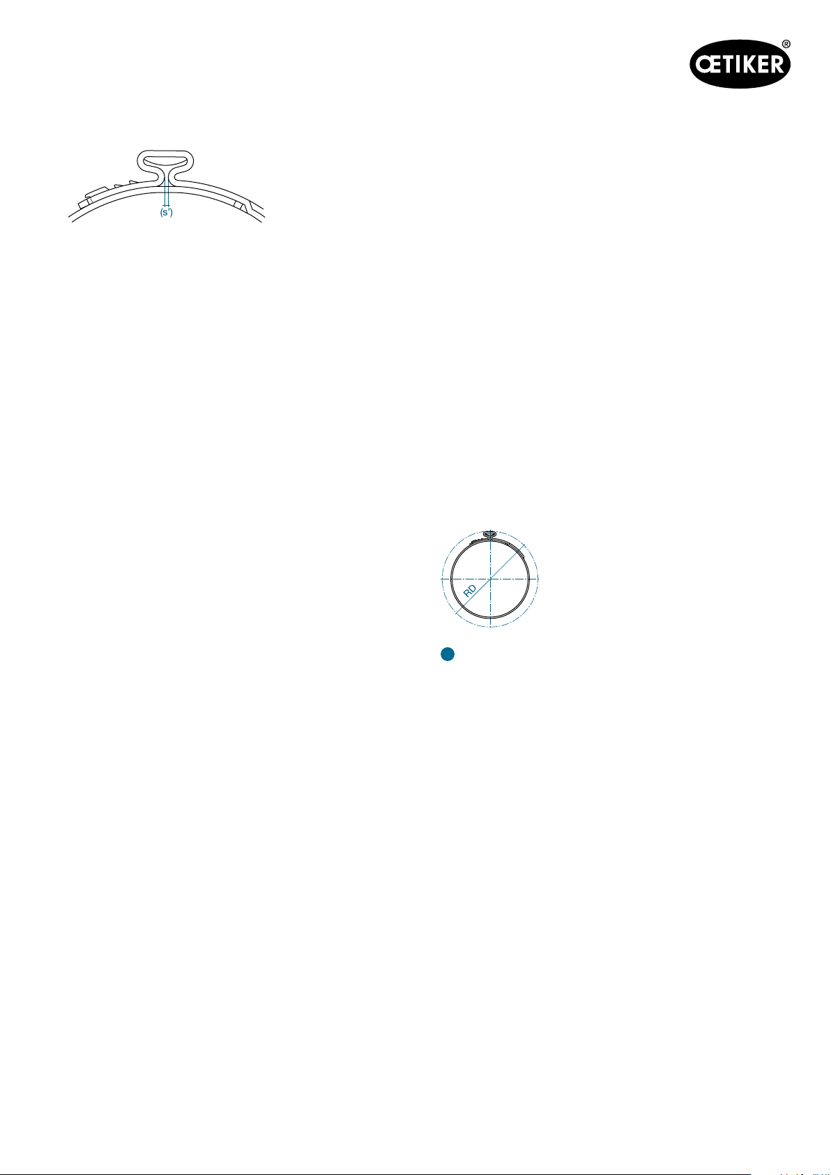
Note: the above sketch shows the appearance of a closed
“ear” (s’); it does not necessarily indicate an eective closed
assembly.
The following applies as a guideline: To determine the correct
clamp diameter, push the hose onto the attaching material,
(e.g. the nipple), and then measure the outer diameter of the
hose. The value of the outer diameter must be slightly above
the average value of the diameter range of the clamp to be
selected. A clamp can only be considered adequately closed
when the ear width (s) has been reduced by at least 40%, and
the correct closing force was used for assembly.
Block closure
Block closure means that, during the applied closing force,
both ear shanks of one ear clamp touch each other. The
closing force applied after the occurrence of block closure is
absorbed by the block closure and not transferred to the parts
being clamped. If a statement about the eective closing force
acting on the parts being clamped during closure is required,
a block closure should be avoided.
Mechanical interlock
The interlock is a mechanical system for joining the clamp
ends to permit closure. Some interlock designs can be
opened for radial installation prior to closure.
Assembly Recommendations
The clamp “ear” is deformed with a constant tool jaw force
– this practice is referred to as “force priority closure”. This
assembly method ensures that a uniform and repeatable
stress is applied to the joint in addition to a consistent tensile
force on the clamp interlock. Employing this methodology
when closing a 167 series clamp will compensate for any
component tolerance variations, and ensure that the clamp
applies a constant radial force to the application. Fluctuations
in component tolerances are absorbed by variations in the
“ear” gap (s’). Clamp installation monitoring and process data
collection are available by incorporating an “Electronically
Controlled Pneumatic Power Tool” Oetiker ELK in the
assembly process.
Closing force
The closing force must be chosen to give the required material
compression or surface pressure and should be qualified
by dimensional evaluation and experiment. The resistance
against the clamp equals the applied force, so the closing
force is greatly reduced when compressing a soft material.
The table below gives the maximum applied closing force
for clamp and material dimensions when compressing and
sealing relatively hard synthetic materials.
Complete process monitoring, including 100% documentation
is available using the Electronically controlled pneumatic
pincer ELK.
Rotation diameter
The rotation diameter (RD) of an assembled clamp can be
critical design information for applications that rotate in close
proximity to adjacent components. Many factors can influence
this final assembly diameter including compression, “ear”
gap “s” and material thickness. It is recommended that all
variables be considered and evaluated prior to specifying a
rotating diameter.
!
Important
– The ear height is naturally given. Do not influence the ear
height, either by changing the ear gap or with built-in hold-
down devices in installation tools.
– Single tool stroke closure only, do not apply secondary
crimping force.