3 Stage Conveyor.pdf - 第17页
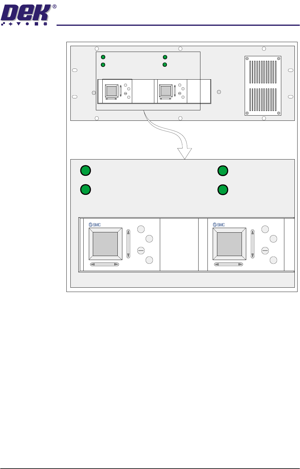
TECHNIC AL REFEREN CE MECHANICAL DETAIL Chapter Issue 2 May 02 High Throughput Conveyor Manual 1.11 Figure 1-8 3-S tage Conveyor Contr oller (M27) 1/3 ST AGE OPERA TION 1/3 ST AGE OPERA TION F AST TRANSFERS DISABLED F AS…
TECHNICAL REFERENCE
MECHANICAL DETAIL
1.10 High Throughput Conveyor Manual Chapter Issue 2 May 02
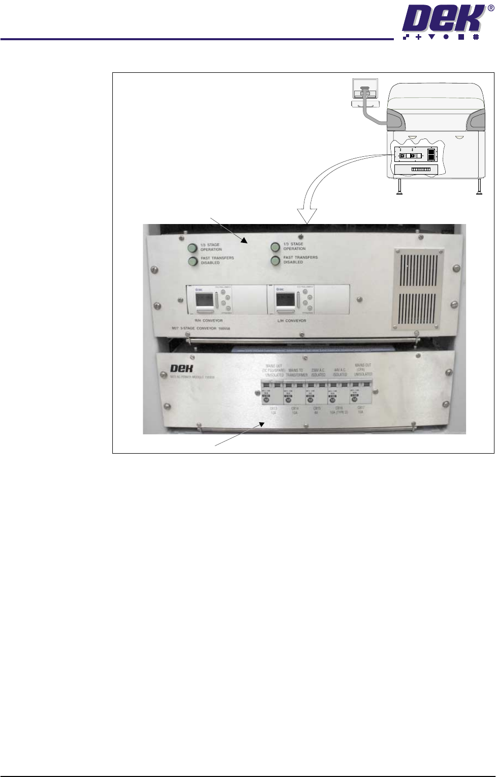
Figure 1-7 M27 Overview
3-Stage/Single
Stage Mode
For three stage mode, both 1/3 Stage Operation buttons must be OFF (LED
extinguished). The LCD screen on the PLC displays ‘3 Stage’ on the top line.
For single stage mode, both 1/3 Stage Operation buttons must be ON (LED lit).
The LCD screen on the PLC displays ‘1 Stage’ on the top line.
Fast/Normal Mode For a conveyor to operate in fast transfer mode, both Fast Transfers Disabled
buttons must be OFF (LED extinguished). The LCD screen on the PLC displays
‘Fst.Trans.’ on the bottom line for 5 seconds on power up or when the button
is switched to OFF.
For a conveyor to operate in normal transfer mode, both Fast Transfers
Disabled buttons must be ON (LED lit). Normal transfer mode is not displayed
on the PLC.
M23 ac Power Supply
Rear View Machine
M27 3-Stage Conveyor Controller
1/3STAGE
OPERATION
1/3STAGE
OPERATION
FASTTRANSFERS
DISABLED
FASTTRANSFERS
DISABLED
M27 3-STAGECONVEYOR 160558
LANEA (R/H) LANEA (L/H)
+
OK
ESC
+
OK
ESC
TECHNICAL REFERENCE
MECHANICAL DETAIL
Chapter Issue 2 May 02 High Throughput Conveyor Manual 1.11
Figure 1-8 3-Stage Conveyor Controller (M27)
1/3 STAGE
OPERATION
1/3 STAGE
OPERATION
FAST TRANSFERS
DISABLED
FAST TRANSFERS
DISABLED
R/H CONVEYOR L/H CONVEYOR
+
ESC
OK
+
OK
ESC
1/3 STAGE
OPERATION
1/3 STAGE
OPERATION
FAST TRANSFERS
DISABLED
FAST TRANSFERS
DISABLED
M27 3-STAGE CONVEYOR 160558
LANE A (R/H) LANE A (L/H)
+
OK
ESC
+
OK
ESC
TECHNICAL REFERENCE
MECHANICAL DETAIL
1.12 High Throughput Conveyor Manual Chapter Issue 2 May 02
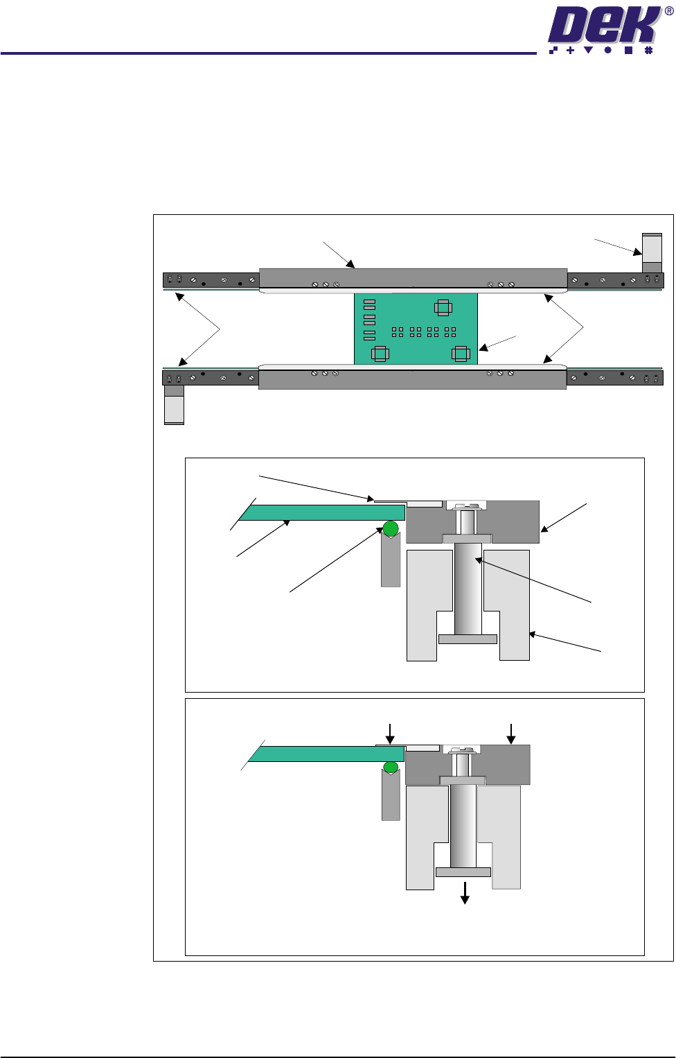
Board Clamps A board clamping arrangement is utilized to secure the board during the print
process and to minimize board distortion. A pneumatically operated piston, (via
a 24V switched solenoid 16SOL10 from the machine controller), lowers the
board clamp and foil, trapping the board on the transport belts. On completion
of the print stroke the board is released by activation of the pneumatic solenoid.
An in-line pneumatic exhaust ensures quick release of the board clamps.
Figure 1-9 Board Clamping Arrangement
Transport Belt
Rail
Piston
Metal Foil
Board Clamp
Board
Pneumatic Piston Driven Downwards
Board Trapped Between Foil and Transport Belt
Board Clamp and Foil Lowered
WARNING SHARP EDGE
PATENT No 5157438
WARNING SHARP EDGE
PATENT No 5157438
Transport Belt MotorBoard Clamp
Transport Belts
Metal Foils
Board
Plan View of Print Station Conveyor
Board Free on Transport Belt