Printer 600 Machine Overview.pdf - 第6页
0 $&+,1( 29(59,(: 0 $&+,1( 29(59,(:6 3.6 Technical Reference Manual Chapter Issue 4 May 03 AC Circuit Breaker Panel CCT Breaker Current Rating C CT Break er Function CB13 10A Mains Out - Un-isolated CB14 10A Ma…
0$&+,1(29(59,(:
0$&+,1(29(59,(:6
Chapter Issue 4 May 03 Technical Reference Manual 3.5
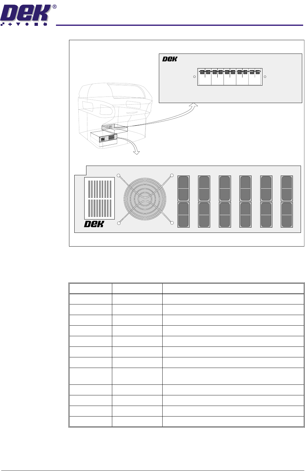
Figure 3-4 Machine Circuit Breaker Panels
DC Circuit Breaker Panel
ac Circuit Breaker Panel
dc Circuit Breaker Panel
M24 DC Power Module 155945
l
o
l
o
l
o
l
o
l
o
l
o
l
o
l
o
l
o
l
o
l
o
l
o
CB1
CB3 CB5 CB7 CB9 CB11
CB2 CB4 CB6 CB8 CB10 CB12
M23 AC POWER MODULE 155938
CB13 CB14 CB15 CB16 CB17
CCT Breaker Current Rating CCT Breaker Function
CB1 2.5A +5V MultiMoves
CB2 1.2A -12V Pressure Amplifier
CB3 1.2A +12V Sensors/MIU
CB4 2A +12V External E Stop
CB5 10A +24V MultiMove (X13)
CB6 1.2A +24V MIU
CB7 6A +24V FPA (Not Used)
CB8 2.5A +24V Camera Lighting, Fans, Paste Roll Lamp, Print
Carriage Brake
CB9 1.2A +24V SW SYS LED/MIU
CB10 10A 24V SW MultiMoves (X11 not used, X12)
CB11 12A 24V SW Steppers/Head Lift
CB12 2.5A Spare

0
$&+,1(29(59,(:
0
$&+,1(29(59,(:6
3.6 Technical Reference Manual Chapter Issue 4 May 03
AC Circuit Breaker Panel
CCT Breaker Current Rating CCT Breaker Function
CB13 10A Mains Out - Un-isolated
CB14 10A Mains to Transformer
CB15 4A 230V - Isolated
CB16 10A 44V - Isolated
CB17 10A Mains Out
0$&+,1(29(59,(:
02'8/(29(59,(:6
Chapter Issue 4 May 03 Technical Reference Manual 3.7
MODULE OVERVIEWS
Machine Control
Enclosure
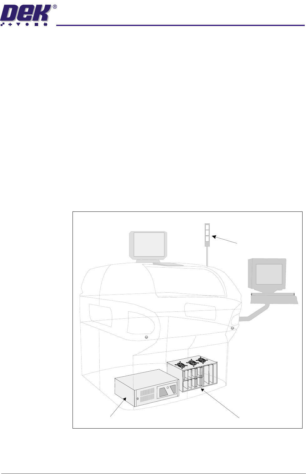
The machine control enclosure provides the drive and control voltages for the
servo and stepper motor systems. The enclosure controls the electrical power
required to activate all solenoids, dc motors, clamps and lamps.
Output of machine sensors signalling the status of the machine are routed
through the enclosure. The foreign machine interface (FMI) is fed via the
enclosure under the control of the machine PC enclosure.
Machine PC
Enclosure
The machine PC enclosure is the master controller of the machine. Issuing
sequential control commands to slave systems via the machine controller
enclosure, the enclosure analyses the feedback signals and issues further
commands to ensure the correct operation and safety of the machine. Vision
information from the camera is processed by the processor card via the vision
card for the MMI and 2D modules.
MMI Module The man machine interface module (MMI) enables communication and interac-
tion between the user and the machine. This is achieved by the use of the
monitor, keyboard, mouse, tricoloured beacon and the two button control
system.
Figure 3-5 View on Front of Machine
MMI Module Options
MMI Module Options
Machine PC Enclosure Machine Control Enclosure
Beacon