npm-wx_npm-wxs_brochure.pdf - 第3页
Evolved automatic recovery (predicted control) T aking the concept and compatibility of NPM series SPV-DC NPM-DX NPM-WX APC system Automatic recovery option Remote operation option Automatic changeover option iLNB PCB in…
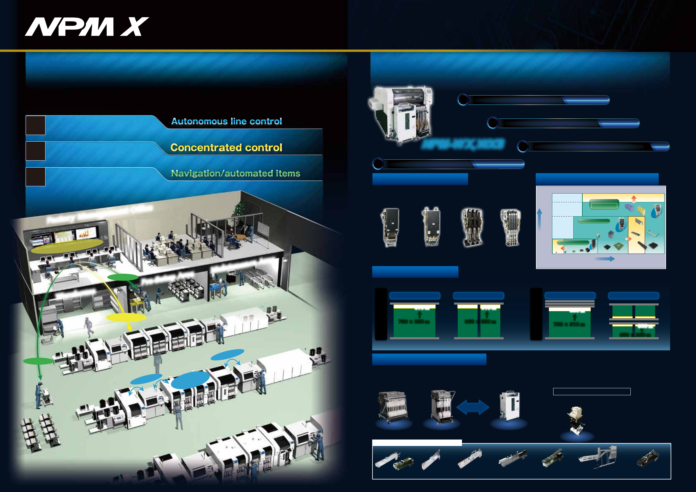
New platform to realize Smart Manufacturing
[2]NPM-WX、WXS's features
NPM-WX,WXS
*L-sized one is available separately, depending on the component size.
3-slot stick feederSingle stick feederAutoload feeder
Thin type
single tape feeder
Tape feeder
Attachable to 30-/17-input feeder carts
Stackable stick feeder (s)*
Multi-functional
transfer unit
1
2
3
1
3
2
Navigation
Navigation
Automatic
Error Recovery
Remote Operation
Pre-Setup Area
Warehouse
Maintenance Area
Factory Management Office
Integrated Floor Management
Developing high-quality, high-throughput unmanned floor
Stable operation based
on the autonomic function
Labor-saving, improved
utilization
Reduced work variations
“Smart manufacturing”
More line throughput, better quality and lower cost with
fully automated mounting system floor
Floor management system and remote operation option
Feeder setup navigation, component supply navigation
and automated items
[1]Panasonic's next generation of mounting production (X series) concept
APC system and automatic recovery option
*APC-MFB function of NPM-DX、WX、WXS is under development.
Evolved basic performance
Maximized actual throughput
Minimization of human-dependent work
0201 03015 0402 0603
40(mm)
30(mm)
12(mm)
3(mm)
□
6
□
32
【mm】
□
45
150×25
120×90100×40
4NH/3NH V2
Lightweight
16-nozzle head V2
*:NPM-WX(Tact for Lightweight 16NH V2 × 2 head)
Greater versatility in supply units
Increased PCB adaptability
Long PCB
750 × 550 ㎜
↑ ↑
610 ㎜ 610 ㎜
350 × 550 ㎜
Short PCB
Long PCB
750 × 510 ㎜
↑
↑
590 ㎜
350 × 260 ㎜
Short PCB
2 PCBs Transfer for reducing loss2 PCBs Transfer for reducing loss
300 ㎜
Increase in transportable PCB size (The following figures show increases compared to NPM-W2.)
The feeder carts of both the NPM-W (30-input) and the NPM-D (17-input) series are now installable;
in addition to that, the interchangeability between a feeder cart (17-input) and newly developed single
tray feeder (24-product type) allows you to replace them by each other on your own.
1
Increased productivity/quality
Evolved basic performance
Max.speed : 86 000cph
IPC9850(1608) : 64 500cph
Placement accuracy : ±25μm
*
*
Lightweight
8-nozzle head
4-nozzle head3-nozzle head V2
Improved ability to support components
component height
component dimensions
Expanded
Lightweight 16NH V2
Lightweight 8NH
Expanded
Component weight:50g
Placement load :100N
Expanded
Single Lane spec
Dual Lane spec
Interchangeable
Single tray feeder
(24 Component types)
Automates splicing of 8 mm-width tape
(paper/embossed).
Automatic tape splicing unit
Feeder cart
(30 inputs)
Feeder cart
(17 inputs)
Machine name: ATSU
Model No.: NM-EJW7A
APC-FB/FF
APC-MFB2
Evolved automatic recovery (predicted control)
Taking the concept and
compatibility of NPM series
SPV-DC
NPM-DX
NPM-WX
APC system
Automatic recovery option
Remote operation option
Automatic changeover option
iLNB
PCB information communication function
AOI information display option
Host communication option
NPM−DGS Data Creation System
LNB
Placement head maintenance Feeder maintenance
Good use is made of the machine's self-diagnosis function to
automatically detect the maintenance timing of the placement
head. In addition, the maintenance unit can be used to keep the
placement head in working condition without requiring skills.
Independent of operator skill, the feeder maintenance unit
automatically performs feeder performance inspections and
calibrations. Its combined use with the PanaCIM maintenance
module can automatically prevent the inclusion of non-conforming
feeders into production.
Component supply navigator option Parts supply navigator option
It is a support tool to navigate efficient setup procedure. The tool
factors in the amount of time it takes to perform and complete
setup operations when estimating the time required for production
and providing the operator with setup instructions.
This will visualize and streamline setup operations during setup for
a production line.
It is a parts supply support tool to present an efficient sequence of
parts supply. Taking into account the length of time before parts
shortage occurs and the least time-wasting moving path possible,
the tool provides the operator with instructions for parts supply.
This makes parts supply more efficient.
Automates the inspection of major parts
which affect the feeder performance and the
calibration of the pickup position.
Feeder maintenance unitFeeder maintenance unit
Manages the assets of
mounting floor, such as
machines, heads and feeders,
notifies the assets nearing
their maintenance dates, and
records maintenance
histories.
PanaCIM maintenancePanaCIM maintenance
Measures the“indentation load”
imposed by the placement head, and, as
the amount of change from the
reference value, displays the measured
result on the machine’s monitor or LNB.
To automate the inspection and
maintenance of the placement
head.
Load checker(Under development)Load checker(Under development)
Head maintenance unitHead maintenance unit
Inspects the pneumatic
circuit condition
Head diagnosis functionHead diagnosis function
Checks the placement blow
status
Blow error detectionBlow error detection
*1
Inspection option before pick-up
Thin-type single feeder
attachment (option)
*2
REF
REF
REF
LNB
●Monitors the error status during production,
and applies Interlock to defective feeders
Autonomous line control
Concentrated control
Navigation
Automated items
Maximized actual throughput
2
【Automatically resume production after pickup position teach 】
*No tape feed
When pickup/recognition error occurred, the machine automatically corrects the pickup position without stopping, and resumes production.
That improves machine operation rate.
(Components: 4
mm
embossed (black)/ 8
mm
paper/embossed (black) tape component. *Embossed tape (transparency) is not supported.)
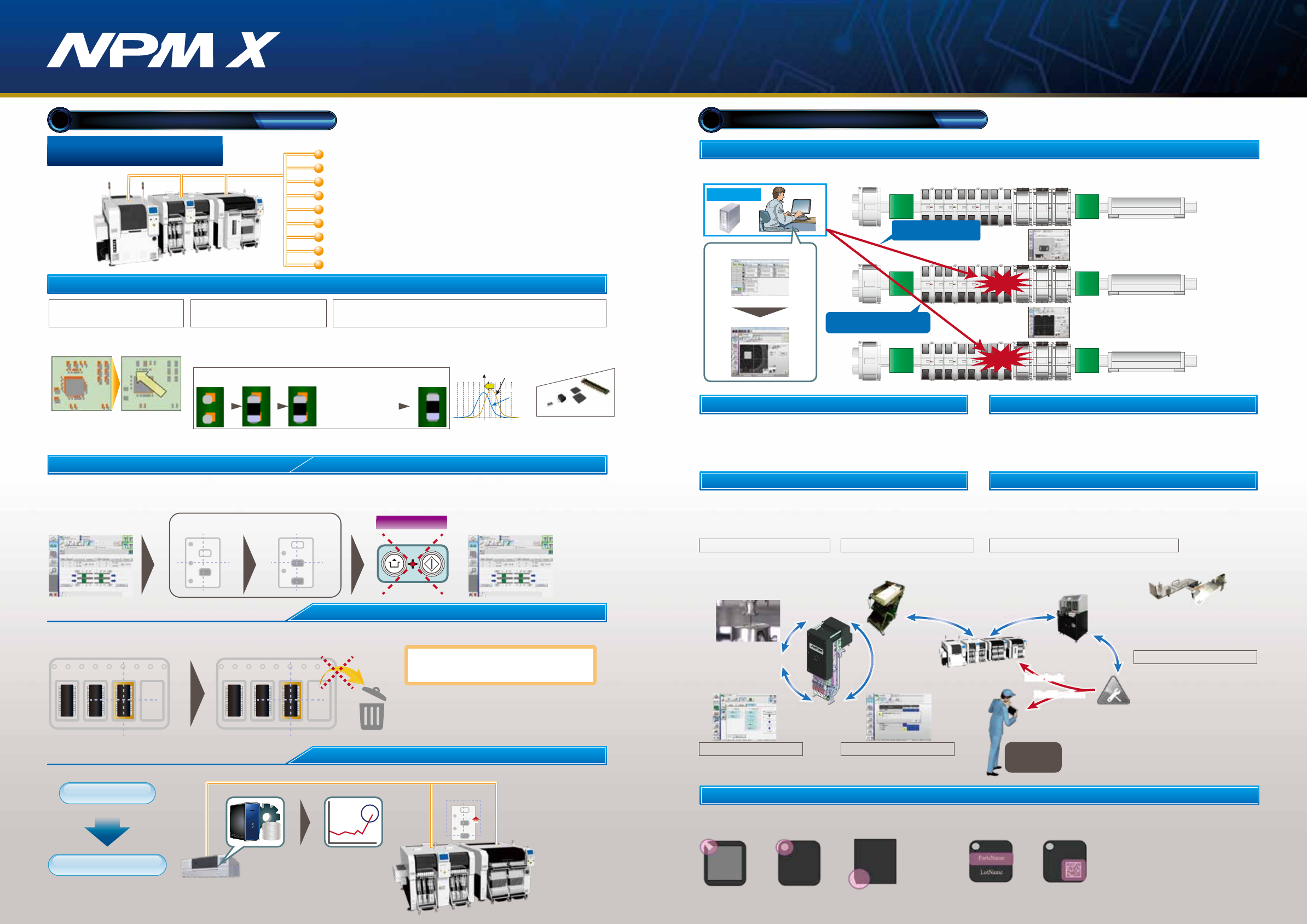
Automatic recovery option
Pickup position automatic teach in case of an error
In production
Automatic feed
Automatic teach
Error Production resume
Unnecessary
Nonstop
Re-pickup of error component (retry)
【In case of an error: re-pickup (retry) at the current position】
In case of a pickup error, retry pickup without feeding tape. It reduces discard components.
Pickup error
Pickup position
Pickup position
Re-pickup (retry)
No discard component because
tape is not fed.*
□ When re-pickup (retry) is succeeded,
the error is not counted
□ The number of re-pick (retry) counts can be set.
* : When re-pickup (retry) is succeeded.
Automatic trend analysis
Automatic recovery/teach
Mounting condition monitoring
Variations of pickup error rate detection
Pickup position
teaching
LNB automatically analyzes the variation of pickup/recognition error rate and instructs the machine to perform teaching to prevent machine error stop.
Minimization of human-dependent work
3
Remote operation option
Recovery by remote operation is available for the error of which recovery can be made based on human judgment alone.
This enables concentrated on-the-floor monitoring, eliminating the time lost for the operator to detect error and take appropriate action,
reducing the error recovery time, and thus achieving labor saving and improved operating rate.
Concentrated
monitor room
Operating condition
monitor
Remote operation
Error occurred
Recover after teaching the
pickup position by remote
operation
Pickup
position
error
Component
placement
error
Recover after checking whether
or not components are placed by
remote operation
Machine name: HMU
Model No.: N610154798AA
Machine name: IFMU
Model No.: NM-EJW8A
*Excluding the feeder cart.
*2:The "Thin type single tape feeder" and
"Autoload feeder" require the
"Master jig for thin type single feeder" and
"Attachment for thin type single feeder".
*2:The "Thin type single tape feeder" and
"Autoload feeder" require the
"Master jig for thin type single feeder" and
"Attachment for thin type single feeder".
*1:This function comes standard with the machine
●Usage count
●Error occurrence history
A PC system
Inspect tray or reel components before pick-up to prevent misplacement.
①Polarity inspection ⇒ Detects wrong component orientation
②Component number inspection ⇒ Detects wrong components, traces components.
Average
luminance
Pattern
matching
Chamfering
inspection
Text recognition
(lot number text)
2D code recognition
(lot number text)
Interlock
function
●Interlock for feeders judged non-conforming by IFMU
Notification
Interlock
・Position inspection on APC
offset position
*2
*1 *1
Shift in placement position
Basic concept regarding MFB correction
*1:APC-FB (feedback)/FF (feedforward): 3D inspection machine of another company can be also connected. (Please ask your local sales representative for details.)
*2:APC-MFB2 (mounter feedback2): Applicable component types vary from one AOI vendor to another. (Please ask your local sales representative for details.)
APC-FB
Feedback to the printing machine
Feedforward to the placement machine
Feedforward to AOI / Feedback to the placement machine
APC-FF
APC-MFB2
-25 +25
Before MFB correction
(shift in center of distribution)
After MFB correction
(shift in center of distribution)
lead component
Chip
component
Lower electrode
component
MFB-ready components
Connector
・Based on the analyzed measurement data
from solder inspections, it corrects printing
positions.(X,Y,θ)
・The system analyzes AOI component position measurement
data, corrects placement position (X, Y, θ), and thereby
maintains placement accuracy.
Compatible with chip components,
lower electrode components and lead components
Shifted solder Correction data
of shifted solder
Post-printing
inspection
Measures and inspects
misalignment placement
position data of
Placement and land
standards
After reflow
Standard placement
inspection
Standard solder
placement
Chip components(0402C/R ∼)
Package component (QFP, BGA, CSP)
・It analyzes solder position measurement data,
and corrects component placement positions
(X, Y, θ) accordingly.
NPM at the line head recognizes marks, and forwards mark
information to downstream NPMs. That eliminates the need for
the downstream NPMs to recognize the marks.
Information on components judged NG by AOI is displayed both
on AOI and NPM.
Mark recognition
①AOI is used to pinpoint target NPM
②The target NPM is put in a warning state,
and information from AOI is displayed on the screen
M2M iLNB
(Model No.NM-EJS5B)
*
Collective control of your line composed not only of Panasonic’s
machines but of third vendors’ through a single PC provides
support for your actual production, quality control and processing.
Panasonic is ready to take on the interface between its machines
and third vendors’.
NPM-DGS
LNB
(FA
PC)
LNB
(FA
PC)
*For details, refer to the catalogue or specification for the integrated line management system“iLNB.”*For details, refer to the catalogue or specification for the integrated line management system“iLNB.”
CM Line
NPM-DGS
*1、2
PT200
*1
FAPC
(LNB)
○
○
○
○
NPM X series line
①
②
Information from AOI is displayed on the
screen of the target mounting machine
Type: Flip
M/C No.xx
Fdr ADR xx
Noz Pos xx
AOI
NPM-WX
NPM-DX
NPM-DX+NPM-TT2 Line
iLNB
PLC PLC
Comprehensive control using system software
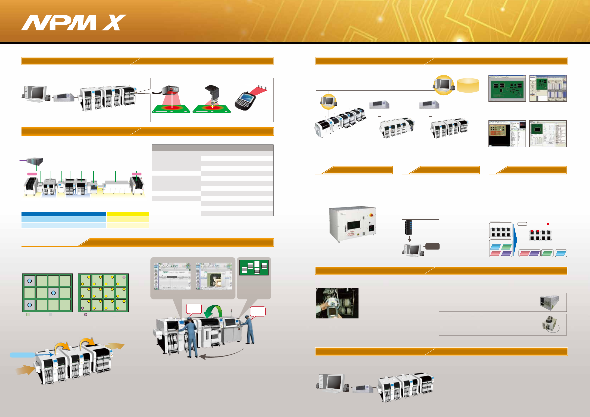
Changeover ability Automatic changeover option
Supporting changeover (production data and rail width adjustment)
can minimize time loss
●PCB ID read-in type
PCB ID read-in function is selectable from among 3 types of external scanner,
head camera or planning form
External scanner
Head Camera Planning form
Non-Panasonic
Non-Panasonic
Non-
Panasonic
PanasonicPanasonic PanasonicPanasonic
Item Non-Panasonic
Panasonic
Information collection/display
Automatic changeover
Bad mark recognition
[Subject for communication]
Pattern mark recognition
Good Bad Master mark
Bad mark is scanned at the
first machine.
All marks are recognized at the first
machine and downstream machines
only recognize master marks.
*Please refer to“Specification”booklet for details.
①Power Supply Station:
Batch Exchange Cart Setup ‒ Provides power to all
feeders in cart. Feeder Setup ‒ provides
power to individual feeders.
②Component Verification Station:
Additional to the power supply station, Component
Verification feature is added to this model.
The station will navigate you to the location where
feeders need exchange.
●Two types of Support Stations are available.
Off-line setup support station
Component Verification option
With the support stations, offline feeder cart setup is possible even
outside of the manufacturing floor.
Prevents setup errors during changeover Provides an increase
of production efficiency through easy operation
*Wireless scanners and other
accessories to be provided
by customer
●Preemptively deters component misplacement
Prevents misplacement by verifying production
data with the barcode information on changeover
components.
●Automatic setup data synching function
The machine itself does the verification,
eliminating the need to select separate setup data.
●Interlock function
Any problems or lapses in verification will stop
the machine.
●Navigation function
A navigation function to make the verification
process more readily understandable.
Data Creation System
NPM -DGS(Model No.NM-EJS9 A)
This is a software package that provides integrated management of component library
and PCB data, as well as production data that maximizes mounting lines with
high-performance and optimization algorithms.
Library
database
*1:A computer must be purchased separately.
*2:NPM-DGS has two management functions of floor and line level.
Host system
(Users)
Able to standardize the interfacing with your systems
currently used. Provides data communication with
our standard interfaces.
●Events
Outputs a real-time event of equipment
●Other company's component verification
Communicates with your component verification systems
●Component management data
・Component remaining quantity data: Outputs component remaining quantity data
・Trace data: Outputs data linked with component information (*1) and PCB information (*2)
(*1) Requires input of component information with a component verification
option or an other company's component verification system I/F
(*2) Requires input of PCB information with automatic changeover option
Open interface
Host communication option
PCB Info Communication Function AOI Info Display Option
FA PC
(LNB)
NPM X series line
NPM X series line
Function listFunction list
※The iLNB comprises software and a computer (iLNB PC).
PLC PC, communication conversion PLC, and other
devices should be prepared by customers.
⑥Communication function
(GEM・PLC)
①Automatic changeover
⑤E-Link(Feeder write)
①Writing of component data by an external system
Function Details
①Registration of automatic changeover recipe
②Line automatic changeover
③Automatic changeover monitoring
④Line operation monitoring
②
E-Link(Information input)
①Download / edit of schedule
③
E-Link(Information output)
③Machine status output
①Operation information output
②Trace information output
④E-Link(Machine control)
①Machine interlock, Production start control
①SECS2/GEM communication
②OPC communication
③IO/RS-232C communication
Offline Camera Unit
Allows you to import CAD
data and check polarity,
etc., on the screen.
Realizes high productivity
and also allows you to
create common arrays.
Update production data on
PC during production to
reduce the loss of time.
Allows unified management
of the component library
including mounting,
inspection and dispensing.
Customer system
NPM-DGS
Work content
instructions
CAD import Optimization
Component data can be created offline even
while the machine is in operation.
Use the line camera to create component data.
Lighting conditions and recognition speed can be
confirmed in advance, so it contributes to the
improvement of productivity and quality.
Offline Camera(option)
Automated manual routine tasks reduce
operation errors and data creation time.
Example of entire system image:
Automated tasks (excerpt)
PCB
・CAD import
・Offset mark setting
・PCB chamfering
・Mounting point
misalignment correction
・Job creation
・Optimization
・PPD output
・Download
DGS Automation
(option)
In production involving multiple models, setup
workloads are taken into account and optimized.
Optimization of setup(option)
PPD editor
Component library
Manual routine tasks can be automated.
By collaborating with the customer system, the
routine tasks for creating data can be reduced, so
it contributes to a significant reduction in
production preparation time.
It also includes the function to automatically
correct the coordinates and angle of the mounting
point (Virtual AOI).
For more than one PCB sharing common component
placement, multiple setups may be required due to a
shortage of suppy units. In order to reduce the required
setup workloads in such a case, this option divides PCBs
into similar component placement groups, selects a table(s)
for setup and thus automates component placement
operation. It contributes to improving setup performance
and reducing production preparation time for customer
manufacturing various kinds of products in small quantities.
Example:
Auto-run
Line
Line
Setup group
Setup table
Group 1 Group 2 Group 3
A C
B B C AD D