00194563_03_E.pdf - 第8页
1 – 8 Wa ys of identif ication of t he nozzle t ypes. Color ring: Colo r point: Identification by nu mbers: Color marking
1 – 7
Introduction
Nozzle Families and Color Coding
5xx Nozzle Series:
The nozzles of the 5xx series are marked with a color point
and equipped with an adapter.
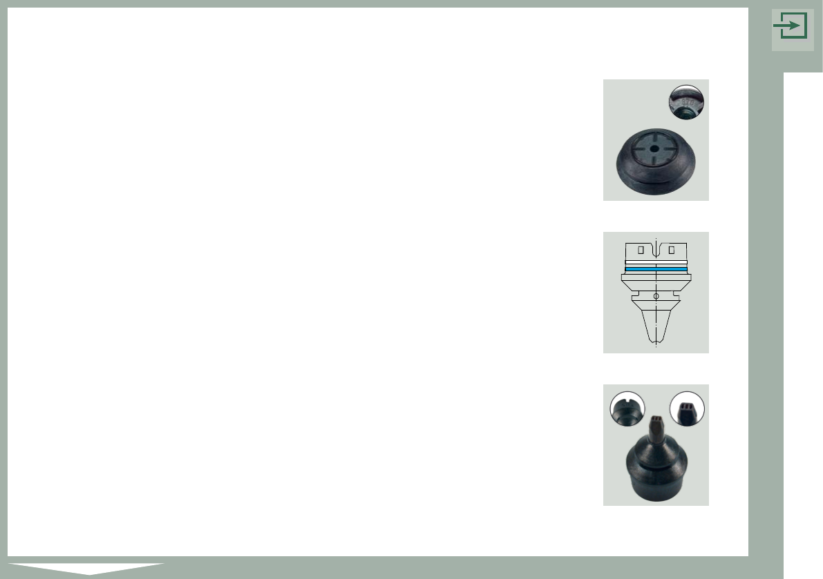
8xx Nozzle Series:
This nozzle series has an imprinting at the inner side with
a 3 digit numeric code.
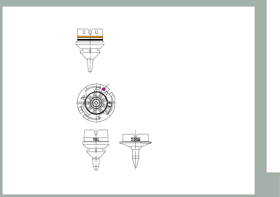
9xx Nozzle Series:
For better differentiation between the nozzle types there are
two color rings around the side of the nozzle base. The first
color ring indicates the nozzle size. The second indicates the
nozzle material.
9xx Ceramic Nozzle Series:
To make the recognition easier the ceramic nozzles are
marked with a 3-digit identification number.
1xxx Nozzle Series:
All nozzles of this family have a 4-digit nozzle type identification number
directly on the nozzle.
Nozzle Series 8xx
Nozzle Series 9xx
(Ceramic)
Nozzle Series 9xx
1 – 8
Ways of identification of the nozzle types.
Color ring:
Color point:
Identification by numbers:
Color marking
1 – 9
Introduction
0° Description of the components
In order to work with uniformly defined package forms, the description of standard
components is subject to four rules. This is referred to as the “0° description”. It allows the
pickup angle for placement to be defined exactly.
To describe the package form of a component, the dimensions should always be
taken from the corresponding data sheet. It should be noted that it is always the
top view of the component that is described.
The display area of the package form (GF) editor always shows the 0° description of a component.
The zero point of the coordinate system is always at the center of the display area in the package
form (GF) editor. The x-axis points to the right, and the y-axis points upward. The component‘s
center point generally corresponds to the zero point of the coordinate system. Rule 1 defines the
alignment of the sides of the component in the x- and y-axis directions.
Rule 1: The long side of a nozzle with a rectangular suction area must be aligned
along the x-axis of the component.
When the component is picked up, the x-axis of the component always points in the same
direction as the long side of the nozzle (exception: special nozzles with 90° rotation).