N7205A130B.pdf - 第363页
7. AIR CIRCUIT DIAGRAM エアー回路図 EJM9DB -10-801-00
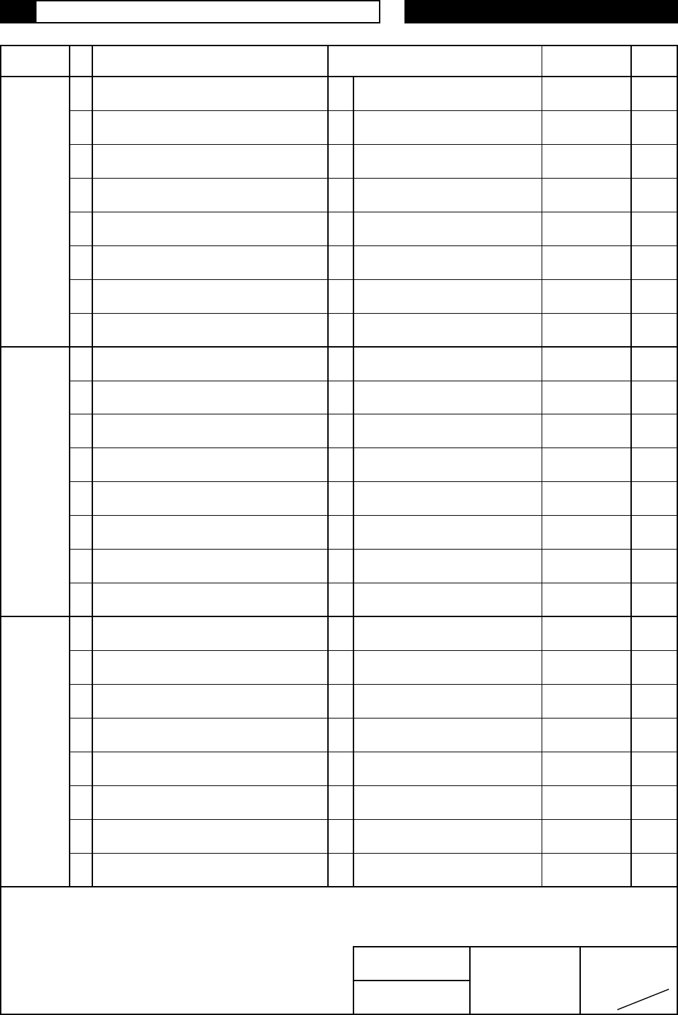
Bit Contents ID
Notes
I/O MAP NPM-WX /-WXS
Address Name
出力/OUT
OT73*
出力/OUT
OP
OP
OT74*
OP
OP
1OP
1OP
1OP
1OP
ページ
16
16
#7_01E3
Output reserve
1
予備出力
Output reserve
0
予備出力
4
予備出力
Output reserve
3
予備出力
Output reserve
2
予備出力
Output reserve
7
予備出力
Output reserve
6
予備出力
Output reserve
5
予備出力
Output reserve
2
L2 基板吸着切り替え#1
L2 PCB Vacuum Pressure Change #1
1
L2 基板排圧切り替え#2
L2 PCB Vacuum Blow Pressure Valve #2
0
L2 基板排圧切り替え#1
#7_01E4
L2 PCB Vacuum Blow Pressure Valve #1
5
L1 基板クランプ上昇2(実装位置#2)
上昇
L1 PCB clamp Up 2 (Mount Pos. #2)
Up
4
L1 基板クランプ上昇1(実装位置#2)
上昇
L1 PCB clamp Up 1 (Mount Pos. #2)
Up
3
L2 基板吸着切り替え#2
L2 PCB Vacuum Pressure Change #2
0
7
L2 基板クランプ上昇2(実装位置#2)
上昇
L2 PCB clamp Up 2 (Mount Pos. #2)
Up
6
L2 基板クランプ上昇1(実装位置#2)
上昇
L2 PCB clamp Up 1 (Mount Pos. #2)
Up
3
4
1
2
NPM-WX /-WXS
Factory solutions Co., Ltd.
図名 パナソニック スマートファクトリー
I/O MAP
ソリューションズ(株)
機種 Panasonic smart
7
↑ Contents:状態のIO表示を示す/Shows I/O status
0:OFF, 1:ON *:状態表示のため、不定
*:Unfixed because status.
5
6

7.
AIR CIRCUIT DIAGRAM
エアー回路図
EJM9DB -10-801-00