YSM20&40_how_to_change_directionPDFA.pdf - 第3页
Service Engineer Service Information SI1407002E - 000 =YSM40_How to change the board flow direction (Tentative measure) 3/ 24 1. Create a w ork spa ce W hen chang ing the board flow direction of YSM40, some parts of the …

Service Engineer
Service Information
SI1407002E-000=YSM40_How to change the board flow direction (Tentative measure)
2/24
Table of contents
1. Create a work space ......................................................................................................................... 3
1.1 Remove the tape cutter duct .................................................................................................... 3
1.2 Remove the slope .................................................................................................................... 5
1.3 Remove the ANC unit ............................................................................................................... 6
2. Change the board flow direction ..................................................................................................... 7
2.1 Change the positions of the Transit position sensors .............................................................. 7
2.2 Change the wiring .................................................................................................................. 11
2.2.1 Change the location of the Entrance and Exit sensors and connector pins (Tentative measure) . 11
2.2.2 Interchange the signal wires (NEXT, PREVIOUS) ........................................................................ 12
2.3 Adjust the optical axis of the sensor ....................................................................................... 13
2.4 Adjustment of the sensor amplifier (KLF-M654N-10) ............................................................. 14
3. Things to do after changing the board flow direction ................................................................ 17
3.1 Change the machine setting................................................................................................... 17
3.2 Adjustments to be performed by the CalibSm........................................................................ 17
3.2.1 “Adj. Conveyor Guide Check Pos.” ............................................................................................... 18
3.2.2 “Adj. Data Check Origin” ............................................................................................................... 20
3.2.3 “Transfer Distance” adjustment .................................................................................................... 23
3.2.4 “ANC Swap”.................................................................................................................................. 24
Service Engineer
Service Information
SI1407002E-000=YSM40_How to change the board flow direction (Tentative measure)
3/24
1. Create a work space
When changing the board flow direction of YSM40, some parts of the machine need to be
removed to create a work space.
This section describes how to remove the parts.
1.1 Remove the tape cutter duct
For the YSM40, 4-Beam type machine, remove the tape cutter duct and the slope to create a work
space.
For the YSM40, 2-Beam type machine with the c-ATS, remove the cutter unit to create a work
space.
Note:
If the tape cutter is detachable and the customer has the tape cutter carrier, remove the tape cutter for
the better workability.
If the customer does not have the tape cutter carrier, remove the slope. (It is the same as the procedure
for the 4-Beam type machine.)
1. Turn OFF the power supply and the air supply.
Caution:
You will need to work under the base. In order to prevent the transformer and the electric part from
shorting out by touching them with a tool (drivers, wrenches and so on), make sure to turn OFF the
power at the main breaker.
Warning:
As the protection cover of the tape cutter is removed during the work, make sure to shut OFF the air
supply at the main valve.
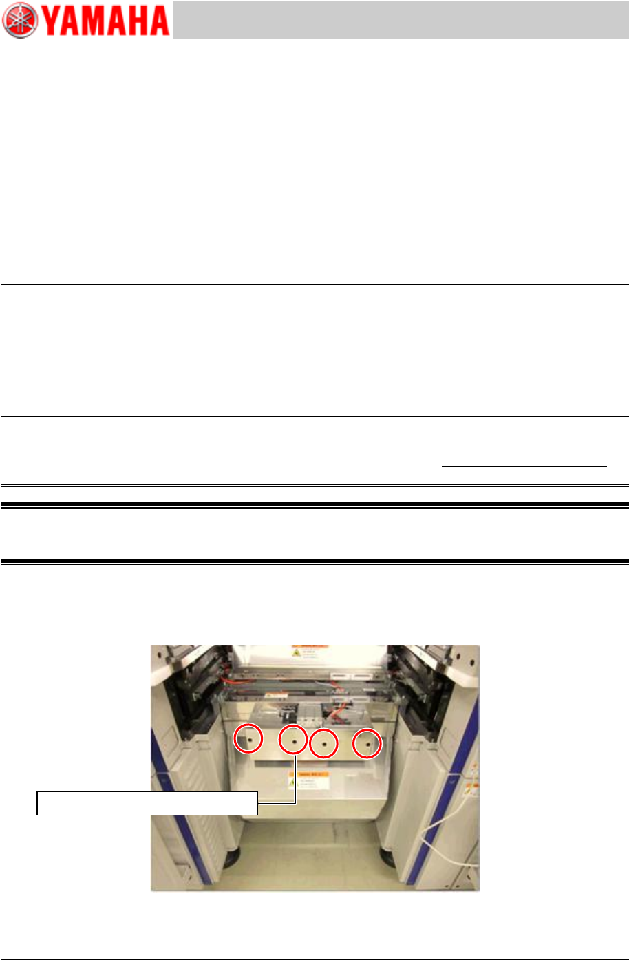
2. Loosen the screws of the tape cutter duct.
Insert a driver into the screw holes (Qty: 4) on the front cover and loosen the screws.
As the screw holes of the cover are U-shaped, you do not need to remove the screws.
Figure 1
Note:
For removing the screws, use a driver 100mm or longer
Use a screwdriver 100mm or longer
Service Engineer
Service Information
SI1407002E-000=YSM40_How to change the board flow direction (Tentative measure)
4/24
Note:
If the cover that protects the driving part of the tape cutter is the old type, remove the front cover.
Use a T-shaped wrench (M4) to remove the eight (8) screws.
3. Remove the tape cutter duct.
Slide the duct downward and then push it. The duct hook on the far side is detached and the duct
can be removed.
Caution:
If the duct is detached from the hook, it drops by its own weight. Make sure to hold it carefully when
removing the duct so that not to drop it on your foot.