00193889-0302_AI_LP-Ausrichtung_DE+EN.pdf - 第26页
PCB alignment unit for SIPLACE S-27 HM / HS-60 / HF-series / X-ser ies / D-series Edition 11/2006 24 This operatio n extends the travel time by 0.5 second s. This option is not taken into acco unt by the time optimizatio…
PCB alignment unit for SIPLACE S-27 HM / HS-60 / HF-series / X-series / D-series
Edition 11/2006
23
2 Assembly instructions
PCB alignment unit
These instructions describe how to install the following PCB alignment units: 2
00118526-01 / 00118525-01 / 00119426-01 / 00119425-01 / 00119678-01 / 00119677-01 /
0
0119858-01 / 00119857-01. 2
2.1 Overview
This option is an additional mechanical stopper that may be needed for: 2
– PCB’s with a aspect ratio of 1:2 (length/width) or shorter
If PCB’s in landscape format (with the short side in moving direction) runs through the machine,
they
have too little lateral guidance and so they can twist a little. 2
This option aligns all PCB’s so that PCB fiducials are always
visible in the search window of the
PCB vision camera. 2
– For PCBs with cut-outs in moving direction:
On PCB conveyors for the existing machine platform, the mechanical stopper (HS-50 / S-25 HM
/ F
5 HM) stops the PCB in a different position than on the new conveyor with laser light barrier
(HS-60 / S-27 HM / HF-series / X-series / D-series). 2
This option ensures that PCB with recesses in moving
direction are always stopped exactly on the
same position on different PCB conveyor systems. 2
2.2 Description of the functions
The PCB is transported into the placement area until the laser light barrier is activated and the
PCB stops. As the first PCB moves in, the lifting table performs a reference run that determines
the PCB thickness. The lifting table then moves up until the PCB is still able to move with the
conveyor belt, and the ‘stopper PCB adjustment’ is level with the PCB. The PCB is then moved
with the conveyor belts against the PCB alignment unit, where it is aligned. Finally, the lifting table
is moved up so that the PCB is clamped and not in contact with the PCB alignment unit. 2
Once the placement process is complete, the lifting table moves the PCB alignment unit and the
PCB
down until the PCB can be moved onwards without interruption. 2
PCB alignment unit for SIPLACE S-27 HM / HS-60 / HF-series / X-series / D-series
Edition 11/2006
24
This operation extends the travel time by 0.5 seconds. This option is not taken into account by the
time optimization function.
2
An electrical switch signals the PCB alignment option to the conveyor control. The station software
outputs a warning message to the operator during the width adjustment process. 2
: The PCB alignment unit must be set manually by the operator.
The maximum component height on the underside of the PCB is still 40 mm. 2
2
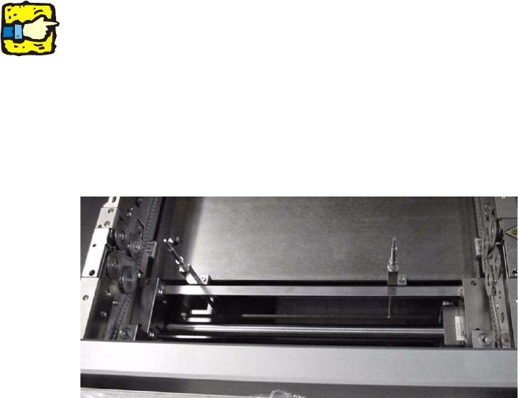
Fig. 2.2.1 PCB alignment unit assembled for double conveyor (HS-60)
PCB alignment unit for SIPLACE S-27 HM / HS-60 / HF-series / X-series / D-series
Edition 11/2006
25
2.3 Parts required
2.3.1 Tools and consumables required
- Set of Allen keys
- Cable ties L x B = 140 x 3,6 mm Item no. 00805141-01 5 - 6 Stück
- Fixing base, self-adhesive Item no. 00805103-01 2 - 3 Stück
2.3.2 Retrofit kit
DC … Double conveyor
SC … Single conveyor 2
Qty PCB alignment unit Description Item no.
1 DC S-27 HM 00118525-xx
1 SC S-27 HM 00118526-xx
1 DC HS-60 / D4 00119425-xx
1 SC HS-60 / D4 00119426-xx
1 DC from SIPLACE HF-series / X-series / D3 00119678-xx
1 SC from SIPLACE HF-series / X-series / D3 00119677-xx
1 DC D1 / D2 00119858-xx
1 SC D1 / D2 00119857-xx
2
2
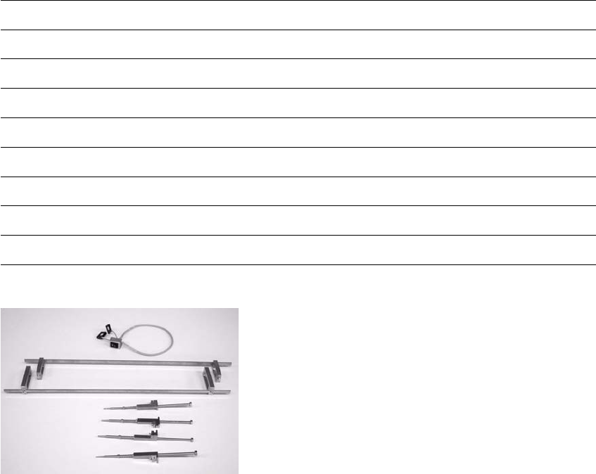
Fig. 2 - 1 Retrofit kit e.g. HF
2
2