SMTAI-PAPER-2020-Richter_Final-2.pdf - 第2页
deposit on the heat exchanger and co oled areas of the heat exchanger b ox and then drip do wn to catch tra ys. T hese systems are typically abo ut 30% efficient in flu x capture and require a hi gh le vel of maintenance…

HIGH-EFFICIENCY, LOW MAINTENANCE FLUX REMOVAL METHOD FOR
REFLOW FURNACES
Paul J. Richter
BTU International, Inc.
23 Esquire Road North Billerica, MA 01862
prichter@btu.com
ABSTRACT
The accumulation of residual flux in solder reflow furnaces
is known to result in product yield losses and maintenance
down time. This is a significant industry problem. Various
techniques are currently used to trap and remove flux
residues from the furnace environment, but the efficiency
and maintenance burden of these methods is not optimal.
Described in this work, is a novel method of capture which
separates flux from the recirculating furnace gas using an
aqueous gas/liquid sequestration process. This system
operates automatically and does not require production line
shut-down for routine maintenance which consists of
periodically emptying a small liquid waste container. This
method is compatible with both Clean and No-Clean type
fluxes. Capture efficiency of different fluxes were tested
and will be reported in this study.
Key words: Reflow Soldering, Flux Management,
Convection Oven
BACKGROUND
The conveyor oven reflow soldering process is now well
established in industry for joining SMT components to
printed circuit boards. Fluxes formulated into solder pastes
to prevent oxidation and aid wetting during the reflow
process produce sticky residues in the oven which, if not
controlled, can drip onto product and accumulate in the
oven. This causes yield losses, equipment down time and
high maintenance costs. A method to remove flux effluents
from process oven gas that is effective, cost efficient and
does not require high maintenance demands has been
elusive even though numerous approaches have been tried
through the years. A new technology for addressing flux
management is discussed in this paper.
COMPOSITION OF FLUX EFFLUENTS
No-clean flux composions now in commercial use typically
have low solids content (~5% by weight). Consequently, a
large percentage of the flux constituents are availible to
vaporise and burn in the oven causing heavy effluent
deposition in the oven and dripping onto product. To gain
information about the composition of the resulting flux
effluent, we reached out to our industry partners and
received samples of flux effluents taken from their
production ovens. A suite of analytical techniques including
ICP-MS, FTIR, GC and XPS was used to characterize the
residue samples. Summary results showed the primary
organic components of the effluent are hydrocarbons with
molecular weights of 200-249 (55-85%) and 250-300 (15-
45%). Lighter hydrocarbons (200-249) generally evolve
earlier in the oven thermal profile, while heavier species
come out later in the profile. The hydrocarbons contain
oxygen (and to a lesser extent nitrogen). The primary
surface structures are C-C, C-H single and double bonds;
however, some O-H, C-O single and double bonds are also
present. The presence of metals was found in the samples
with the largest contributors being: Copper, Potassium,
Silicon, Tin, Zinc, and Iron (see Table 1). The values varied
depending upon sampling location in the oven.
Table 1. Flux Effluent ICP-MS Summary Data
Element
Concentration
(ppm)
Cu
14000
K
1200
P
629
Si
584
Zn
375
Sn
315
Fe
196
Na
61
Al
6.6
Ca
5
Pb
3.4
Mg
2.4
Sb
1.1
METHODS OF FLUX REMEDIATION
Condensation flux management is very common and is
currently the standard of the industry. The condensation
method takes flux laden process gas and generally passes it
through a disposable, or cleanable pre-filter element and
then passes it through a heat exchanger cooled by air, or
water. This cools the gas and allows flux to condense and
deposit on the heat exchanger and cooled areas of the heat
exchanger box and then drip down to catch trays. These
systems are typically about 30% efficient in flux capture and
require a high level of maintenance to keep the heat
exchangers clean and unclogged of flux.
Catalytic oxidation is also currently being used in different
variations. These systems use a catalyst to promote
oxidation of organic compounds to carbon dioxide and
water by increasing the kinetic rate. The catalyst allows the
oxidation reaction to occur at relatively low temperatures of
about 340 to 500°C. As seen in the analysis of flux
effluents, the effluent product contains high and low
molecular weight hydrocarbon compounds and also a
significant amount of metals. Catalytic oxidizers can
effectively dissociate the low molecular weight
hydrocarbons into carbon dioxide and water, but are
ineffective at cracking high molecular weight resinous
species. Catalyst life is generally short due to catalyst
poisoning. Catalyst poisoning occurs when a compound
bonds to the catalyst’s active sites and chemically
deactivates the catalyst function due to the presence of
metals such as : copper, potassium, zinc, tin and iron.
Sometimes methods are used to pre-clean the gas before it
reaches the catalyst to try to extend the life of expensive
catalysts. Also, regeneration cycles can be used to
reactivate the catalysts. Resinous, metal laden flux effluents
are very difficult to clean out of the gas stream with
catalytic methods.
GAS-TO-LIQUID SEQUESTRATION
This is a new flux remediation technology that was
developed with the goal of providing a high-efficiency flux
capture method which requires minimal maintenance and
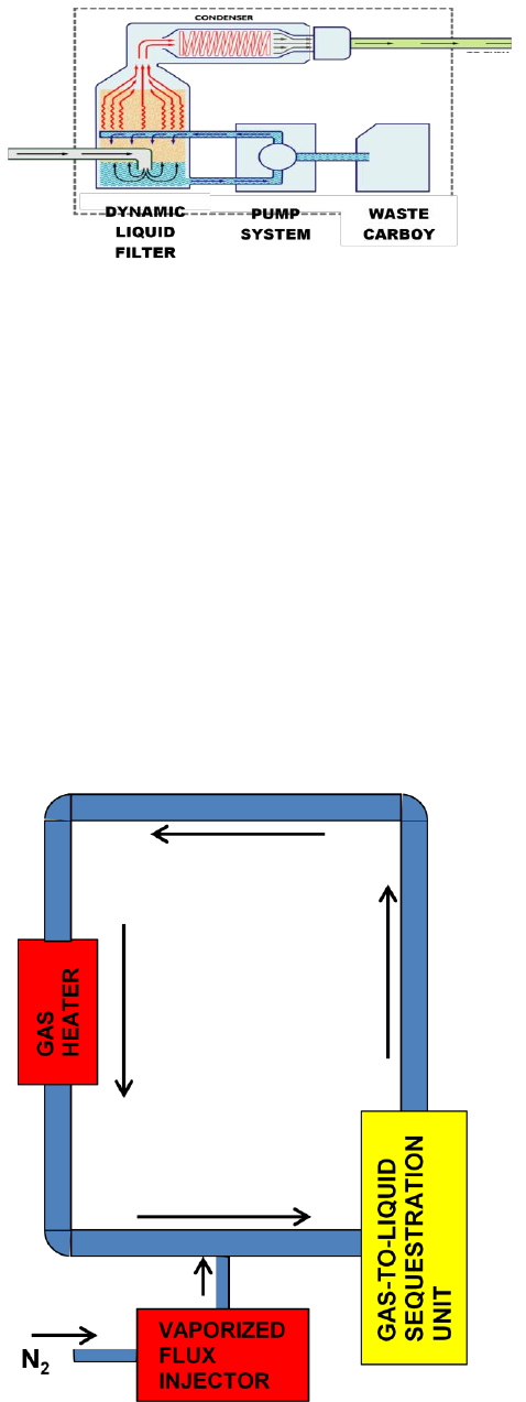
handling of flux residues. This system uses a dynamic
liquid filter to separate flux effluents from the oven gas
stream and suspend them in a liquid medium.
The liquid solution which acts as the transfer medium for
this system is water based, safe to handle, non-flammable
and low cost. The solution is comprised of water that is
provided to the system by plumbing directly to the plant
potable water supply and a concentrated detergent which is
automatically added to the water in the proper ratio.
The gas-to-liquid sequestration unit functions by taking
effluent gas from the oven and passing it through a dynamic
liquid filter where the effluent in the gas stream interacts
with the moving liquid and is entrained and suspended.The
cleaned gas then passes through a condenser to remove
latent moisture from the cleaning process. The gas is then
recycled back to the oven process chamber (see Figure 1).
During operation, a small portion of the solution is diverted
to the waste carboy and then the level of solution is made
back up with an automatic addition of water and
concentrate.
Figure 1. Gas-To-Liquid Sequestration Diagram
RESULTS OF EXPERIMENTS
This data includes a determination of flux capture
efficiency, the ability of the gas-to-liquid method to capture
metals present in the process gas stream and a test to see if
this new process has any effect on solder wetting.
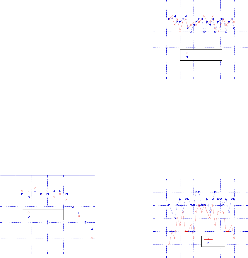
To investigate flux capture efficiency, a laboratory
apparatus was fabricated to simulate oven process gas
operation and introduce a precise amount of burnt and
vaporized flux effluent into the gas-to-liquid unit (see
Figure 2). With this closed circuit apparatus, the gas-to-
liquid sequestration unit was tested independent of any
influence that the oven might contribute. This apparatus can
be run in either nitrogen, or air atmosphere. For this
experiment, nitrogen was chosen to allow testing the system
for potential effect on oven oxygen level.
Figure 2. Test Apparatus Diagram
GAS
IN
GAS
OUT
Two commercial no-clean fluxes were run in this
experimental series. One flux was a high-tack formulation,
the other was a standard formulation. The gas-to-liquid
removal unit was run in two different configurations for this
testing. Configuration #1 was run without using the
drain/replenishment function for the liquid solution. The
reasion for running this configuration was to determine the
inherent capacity of the liquid solution to uptake flux. The
second configuration was run the same as the first except
with the automatic drain/replenishment function activated.
The reason for running this configuration was to test
efficiency during continous automatic operation. For this
series, process gas temperature was maintained at 320°C.
and flux was processed in 200 gram increments. The
capture efficiency was determined by separating captured
flux from the liquid solution and weighing it. The weight of
the captured flux was then expressed as a percentage of the
flux introduced into the test apparatus. Condition 1, running
with a fixed quantity of liquid solution, maintained stable
efficiencies of ~94% until 1600 grams of flux had been
injected into the apparatus (see Figure 3). As more flux was
introduced, a steady decline in efficiency (though still at
high efficiencies) occured as the solution began to saturate.
This result demonstrates a large inherent capacity of the
liquid solution for capturing and holding flux effluents.
Also of note is that both flux types tested performed
essentially the same.
Figure 3. Condition 1 Flux Capture Efficiency
Condition 2, was run in normal automatic mode and the
system was set to perform a partial drain/replenishment
cycle for each 200 gram addition of flux. 5 kilograms of
each flux type were processed in this test. The capture
efficiency for this run was determined by separating the flux
from the waste liquid released in the drain cycle and
normalizing for sample size, comparing it to the cumulative
input flux and again expressing as a percentage of input.
Results from this condition show continuous stable running
efficiencies of between 90 and 95% (see Figure 4). Again,
both fluxes performed essentially the same.
Figure 4. Condition 2 Flux Capture Efficiency
During these efficiency tests which were run in full
nitrogen, the oxygen level was monitored at both the gas
input and output ports of the flux sequestration unit. For
these test runs, oxygen levels were stable and measured at
between 40 – 48ppm (see Figure 5). The oxygen levels
were not negatively affected by the flux capture process.
Figure 5. Inlet and Outlet Oxygen Levels
To investigate the effectiveness of the gas-to-liquid
sequestration method at trapping the metals found in solder
flux effluents, a sample of liquid solution waste from a
sequestration unit running on a commercial reflow line was
prepared for ICP analysis. The results were consistent with
those seen on samples taken directly from the inside of an
oven (see Table 2). This was an interesting result which
indicates a capacity of the new technology to trap metals.
Future work is planned to quantify metals capture by using a
75
80
85
90
95
100
-0.5 0 0.5 1 1.5 2 2.5
Flux #1 (Hi-Tack)
Flux #2
Flux Capture Efficiency (%)
Cumulative Flux Added (Kg.)
75
80
85
90
95
100
-1 0 1 2 3 4 5 6
Flux #1 (Hi-Tack)
Flux #2
Flux Capture Efficiency (%)
Cumulative Flux Added (Kg.)
38
40
42
44
46
48
50
-1 0 1 2 3 4 5 6
Outlet
Inlet
Oxygen (ppm)
Cumulative Flux Added (Kg.)