TR7600 SIII_Electrical_Diagrams_en_v_2_0_3.pdf - 第9页
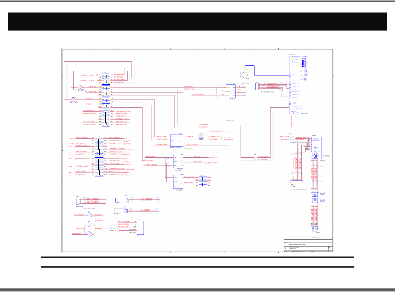
TR7600 SII I User Guide – Electrical Di agrams 1 E LECTRICA L D IAGRA MS 1.1 System Po w er (L) & Conv eyor Figure 1: Sy stem Power (L) & Con vey or

Test Research, Inc.
ii TR7600 SIII User Guide – Electrical Diagrams
Figures
Figure 1: System Power (L) & Conveyor .......................................................................... 1
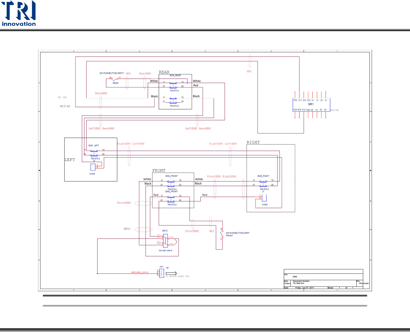
Figure 2: Emergency Stop ................................................................................................ 2
Figure 3: Interlock Left-Right ............................................................................................ 3
Figure 4: Interlock Front-Rear .......................................................................................... 4
Figure 5: Safety Relay ...................................................................................................... 5
Figure 6: System Power (R) & Motion .............................................................................. 6
Figure 7: Sensor ............................................................................................................... 7
Figure 8: X-Ray Source .................................................................................................... 8
Figure 9: Slave Module of DSP Motion Card ................................................................... 9
Figure 10: Contact of DSP Slave Module (CN1A~CN1D&CN5) ................................... 10
Figure 11: Step Motor Driver Switch Set ........................................................................ 11
Figure 12: Air Pressure Solenoid.................................................................................... 12
Figure 13: Camera and FAN .......................................................................................... 13
Figure 14: Sensor ........................................................................................................... 14
Figure 15: Button ............................................................................................................ 15
Figure 16: PLC Block ...................................................................................................... 16
Figure 17: PLC ................................................................................................................ 17
Figure 18: Loader Socket Position ................................................................................. 18
Figure 19: Loader and Unloader Socket Position .......................................................... 18
Figure 20: Loader and Unloader Cable .......................................................................... 19
Figure 21: Unloader Socket ............................................................................................ 20
Figure 22: Inline Connection ........................................................................................... 21
Figure 23: PLC IO ........................................................................................................... 22
Figure 24: Connection Panel .......................................................................................... 23
TR7600 SIII User Guide – Electrical Diagrams
1 E
LECTRICAL
D
IAGRAMS
1.1 System Power (L) & Conveyor
Figure 1: System Power (L) & Conveyor
Test Research, Inc.
2
TR7600 SIII User Guide – Electrical Diagrams
1.2 Emergency Stop
Figure 2: Emergency Stop