ds_MX3600_engl_140110.pdf - 第2页
Automatic X-RAY Insp ection Sy stem Transmission & SFT MatriX Technolog ies GmbH Dornacher S trasse 5 85 622 Feldkirch en (near Mu nich) Germany Phone +49 - 89 - 1894140 - 0 Fax +49 - 89 - 1894140 - 99 E-Mail: info@m…
Automatic X-RAY Inspection System
Transmission & SFT
System Features
High Speed AXI System with up to 3 Images/Sec
(4 sq. inch/sec)
Transmission X-RAY & 3D Slice-Filter
Technology
In-line Board Handling with automatic
width adjust.
130 kV Microfocus X-RAY Tube (sealed)
Dual 3/2 inch Image Intensifier
1k x 1k Digital Camera with programmable
exposure time
3 axes programmable motion with
variable field of view size
Automatic grey-level and geometrical calibration
Barcode Scanner (1D/2D)
MatriX Inspection & Process Software
MIPS Hardware
PC-Station with multi-core processor setup
Windows 7 Platform
MIPS-Inspection Platform
Advanced Algorithm Inspection Library for solder
joint and component inspection
Slice-Filter-Technique (SFT) for double-sided boards
Automatic-Tree Classification (ATC) with
Auto-Rule-Generation
Off-line programming with test-coverage display &
auto program generation
Verification & Process Control
MIPS_Verify link with closed-loop repair
MIPS_SPC Real Time with real-time SPC
FEAT U R E S
The MX-3600 is an In-line X-RAY inspection system with the new MIPS-inspection platform of MatriX Transmission
X-RAY technology is combined with the patented Slice-Filter Technology (SFT) for double-sided or overlaying
applications. The high speed MX-3600 features fully automatic inspection based on a CAD compiled
inspection list and using an inspection model-library for the test-strategy definition.
MIPS_Tune is an off-line programming software
package including automatic CAD import, CAD
compile, inspection parameter setting & rule
generation.
A test coverage display allows optimized inspection
concept analyses & balancing. All relevant
inspection data can be stored and maintained in a
dedicated inspection data base.
The MIPS_Verify module of the MIPS_Process Unit
with its closed-loop repair concept is capable for in-
line or off-line verification using a graphical board
layout display and X-ray image with defect marking.
MIPS-Verify can be linked to combined AOI
inspection platforms.
MIPS_SPC Real Time module provides real-time
process control with immediate production line
feedback.
Automatic X-RAY Inspection System
Transmission & SFT
MatriX Technologies GmbH
Dornacher Strasse 5
85622 Feldkirchen (near Munich)
Germany
Phone +49 - 89 - 1894140 - 0
Fax +49 - 89- 1894140 - 99
E-Mail: info@m-xt.com
Web: www.m-xt.com
Subject to change without notice!
The information in this specification consists
only of general descriptions and/or performance
features, which is not contractually binding. Any
specific performance features capabilities will
only be binding if contractually agreed.
01/2014
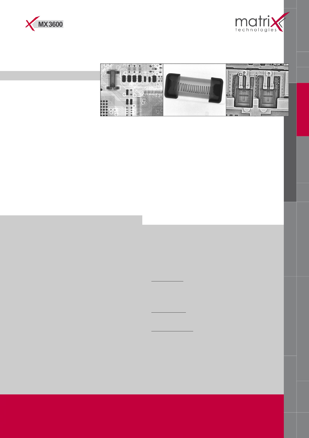
Electronic components and solder-joints
A unique advanced algorithm library is available for
electronic applications specifically for component
and solder-joint inspection on PCB, hybrid or chip-
level assembly processes.
All standard SMD’s and THT/PTH components
Specific BGA and QFN algorithm
Cooling plates/heatsink void inspection
Material analysis and NDT applications
A modular NDT (Non-Destructive-Test) inspection
library features applications for material analysis as
automotive sensors, airbag components or
medical parts.
Automatic object location
Geometrical and profile measurements
Material void inspection
APPLICATIONS
SPECIFICATIONS
Physical Dimension
Dimensions ........................................ 54” (H) x 130” (W) x 62” (D)
........................................... 137 cm (H) x 330cm (W) x 160cm (D)
Footprint ....................................................... 50 sq. ft. (5.16 sq. m)
Weight .............................................................. 4000 lbs. (1800 kg)
Conveyor (SMEMA-IF) ............................... Height 35.5” to 39.5”
.................................................................................. (90 to 100cm)
Safe Operating Temperature .................................... 15° - 32 °C
.......................................................................... optimal 20° - 25° C
Power Consumption .................................................. .1600 Watts
Line Voltage ........................................ 208 to 240 VAC 50/60 Hz
.................................. 40 amps single phase, 2-wire plus ground
Air ..................................................................... 140 NI/min. (6 bar)
Motion System
Programmable X-Y Sample Table with Brushless Servo
Spindle Drives
Driving Distance ..................................................... 500 x 350 mm
Position Repeatability ................................................... +/- 25 µm
Z-Drive .......................................................................... X-Ray Tube
Z-Movement with continuous magnification
(field of view) change
X-Ray Source
Energy ............................................................................ 125kV/ 8W
Power ................................................. Variable Wattage Control
Focal Spot Size ...................................................... 10 – 15 Microns
X-Ray Tube Orientation........................................... Side-Window
Image Detector
Detector Type ...................................... 3”/2” Image Intensifier
Camera ................................................ 1028x1028 Pixels/10 Bit
Video Output (X2.5D) ......................... Camera Link Interface
Video Display ....................................... High Resolution 19” TFT
Image Performance
Inspection Area
Max. Board Handling Size ............................... 14”(X) x 18” (Y)
.............................................................. 355mm (X) x 457mm (Y)
Max. Inspection Area ...................................... 12”(X) x 18” (Y)
.............................................................. 305mm (X) x 457mm (Y)
FOV & Resolution
Field-of-View ........................0.5” (12.7mm) to 1.1” (27.5mm)
Spatial Resolution 20 LP/mm at min. FOV (7.5%MTF)
Assembly Clearance
Topside (incl. Board Thickness): ........................ 0.5” (12.7mm)
Bottom side (excl. Board Thickness): ............... 1.5” (38.1mm)
Safety / Regulatory
Full safe, interlocked enclosure. Complies with all U.S. and
International standards for cabinet radiography systems.
CDRH directives / CE compliant.