JX-100_SPE_EN06.pdf - 第2页
Impor tant (1) No part of this document m ay be copied or reproduced without the pr ior permission of JUKI Corporation. (Including s oftware and prog ram) (2) The content s of t his document are subj ect to chang e witho…
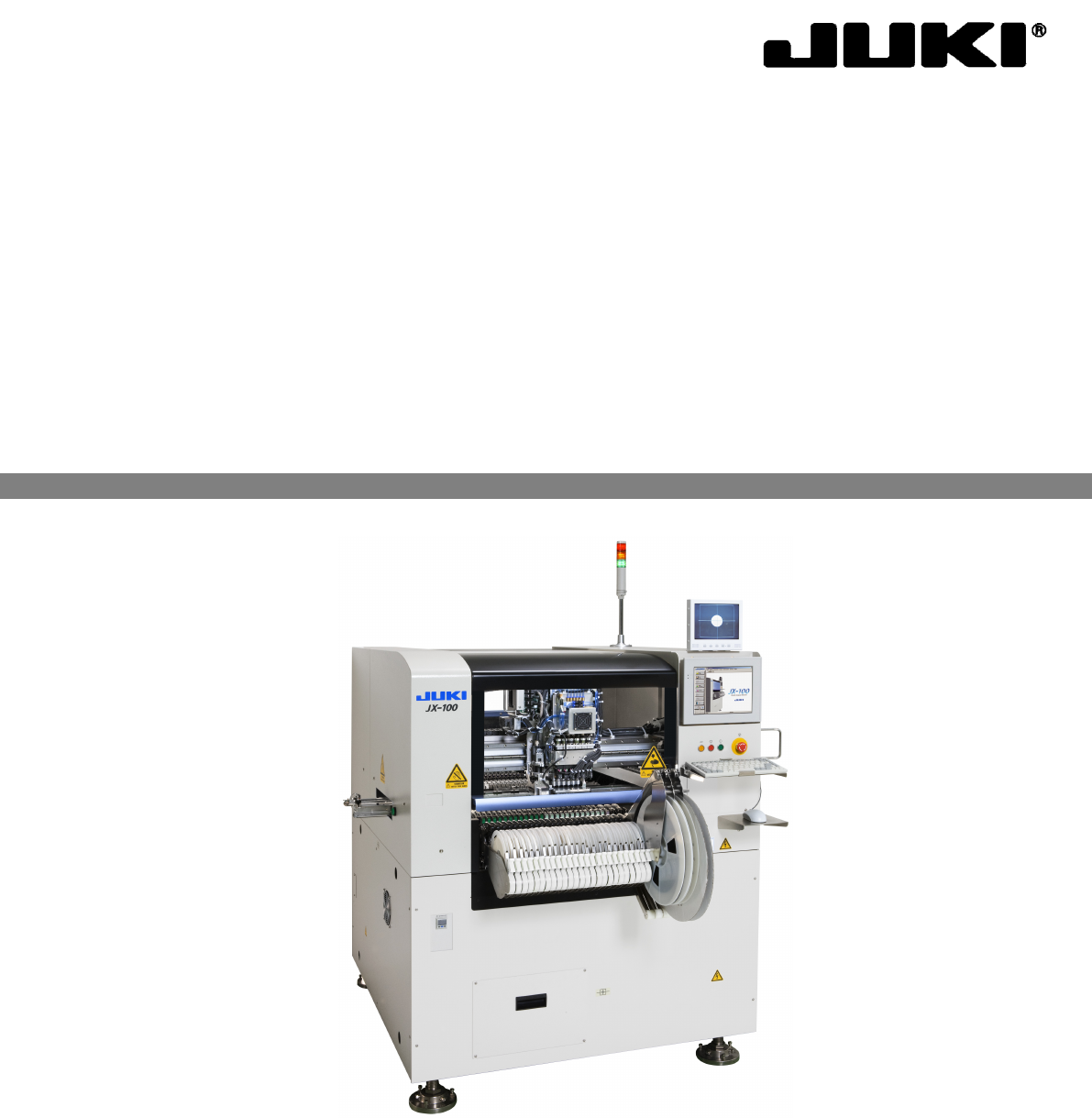
JX-100/JX-100 LED
PRODUCT SPECIFICATIONS
Flexible Compact Mounter

Important
(1) No part of this document may be copied or reproduced without the prior
permission of JUKI Corporation. (Including software and program)
(2) The contents of this document are subject to change without notice.
(3) This manual is prepared with extreme care. However, if you have any question
or find any error or omission in writing, contact our dealer or JUKI Corporation.
(4) JUKI Corporation shall disclaim all the responsibility for any trouble resulting
from the user's abnormal operation regardless of Item (3).
(5) Microsoft,Windows are registered trademarks or trademarks of Microsoft
Corporation in the United States and /or other countries.
The company names and product names mentioned in this document are
generally registered trademarks or trademarks of the respective companies.
TABLE OF CONTENTS
1. GENERAL ..........................................................................................................................1
2. FEATURES ........................................................................................................................1
3. SYSTEM CONFIGURATION .............................................................................................3
3.1 JX-100 System Configuration....................................................................................3
3.2 JX-100 LED System Configuration ............................................................................4
4. SPECIFICATIONS..............................................................................................................5
4.1 Mechanical/Electrical Specifications..........................................................................5
4.1.1 Machine dimensions ............................................................................................6
4.1.2 Mass....................................................................................................................6
4.2
Component placement Cycle Time (A Number of Components to Be Placed Per Hour).7
4.3 Nozzles......................................................................................................................7
4.4 Applicable Component...............................................................................................8
4.5 Component Placement Accuracy at X, Y and θ .........................................................8
4.6 Applicable PWBs.......................................................................................................9
4.6.1 PWBs transport direction .....................................................................................9
4.6.2 PWB sizes and Mass...........................................................................................9
4.6.3 Allowable value of board warp.............................................................................9
4.6.4 Limitations on PWBs............................................................................................9
4.6.5 PWBs clamping method.....................................................................................11
4.7 Function correcting the PWB positions....................................................................12
4.7.1 PWB positioning reference.................................................................................12
4.7.2 Field of vision for recognizing the PWB reference marks...................................12
4.7.3 Window size for recognizing the PWB reference marks.....................................12
4.7.4 Kinds of recognition marks and corrective method ............................................12
4.7.5 Shapes of each mark to be recognized..............................................................13
5. Standard Functions and Options..................................................................................16
5.1 Standard functions...................................................................................................16
5.1.1 Bad mark recognition.........................................................................................16
5.1.2 Liquid crystal touch panel
...................................................................................16
5.2 Options ....................................................................................................................16
5.2.1 Feeder floating detecting sensor (Option for the factory setting)........................16
5.2.2 Vacuum pump (Option for the factory setting)....................................................17
5.2.3 Height measuring function (HMS, option for the factory setting)........................17
5.2.4 Leakage breaker (Option for the factory setting)................................................17
5.2.5 Rear bank (Option for the factory setting)..........................................................17
5.2.6 Main line filter (Option).......................................................................................17
5.2.7 HOD (Option).....................................................................................................17
5.2.8 EPU (Option)......................................................................................................17
5.2.9 Air compressor Assembly (Option )....................................................................17
5.2.10 A simple Buffer (Option only for JX-100)..........................................................18
5.2.11
Lighting unit of solder recognition
(Option for the factory setting only for JX-100 LED)
...............................................18