00195044-12_UM_VisionTeachStation_DE EN.pdf - 第112页
3 Ordering information and package supplied Vision Teach Station User Manual 3.2 Cameras and assembly kits 05/2014 Edition 112 3.2.5 Camera, type 29/30 with assembly kit - item no. 03047374-xx/03086726-xx (option) 3 3 Fi…
Vision Teach Station User Manual 3 Ordering information and package supplied
05/2014 Edition 3.2 Cameras and assembly kits
111
3.2.4 Camera, type 28 with assembly kit - item no. 03047373-xx (option)
3
3
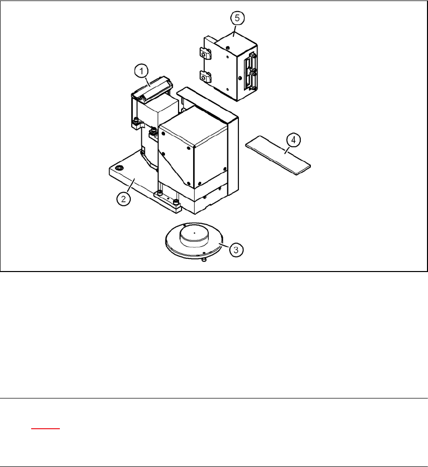
Fig. 3.2 - 6 Camera type 28 - parts
3
(1) Component camera C&P12, type 28, 18 x 18, digital, item no. 03014449-xx
(2) Mount for camera, type 28/29, item no. 03039479-xx
(3) Component support, camera type 28/29, complete, item no. 03039497-xx
(4) Focus point adjustment guide, camera type 28/29, item no. 03046390-xx
(5) Head camera adapter, vision teach station, item no. 03044405-xx
NOTE 3
Figure 3.2 - 6 shows the position at which the component camera (item 1) is mounted on the
vision teach station. On the placement head, the assembly position of the component camera is
turned 180° about the vertical axis.
3 Ordering information and package supplied Vision Teach Station User Manual
3.2 Cameras and assembly kits 05/2014 Edition
112
3.2.5 Camera, type 29/30 with assembly kit - item no. 03047374-xx/03086726-xx (option)
3
3
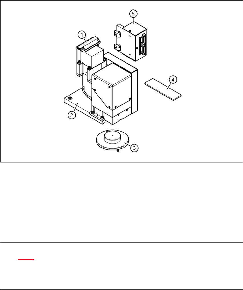
Fig. 3.2 - 7 Camera type 29/30 - parts
3
(1) a) Component camera C&P 6/12, type 29, 27 x 27, digital, item no. 03018637-xx
b) Component camera C&P, type 30, 27 x 27, digital, item no. 03085394-xx
(2) Mount for camera, type 28/29, item no. 03039479-xx
(3) Component support, camera type 28/29/30, complete, item no. 03039497-xx
(4) Focus point adjustment guide, camera type 28/29/30, item no. 03046390-xx
(5) Head camera adapter, vision teach station, item no. 03044405-xx
NOTE 3
Figure 3.2 - 7 shows the position at which the component camera (item 1) is mounted on the
vision teach station. The cable connections for the component camera point towards the pillar of
the vision teach station. On the placement head, the assembly position of the component camera
is turned 180° about the vertical axis.
Vision Teach Station User Manual 3 Ordering information and package supplied
05/2014 Edition 3.2 Cameras and assembly kits
113
3.2.6 Camera, type 36 with assembly kit - item no. 03054654-xx (option)
3
3
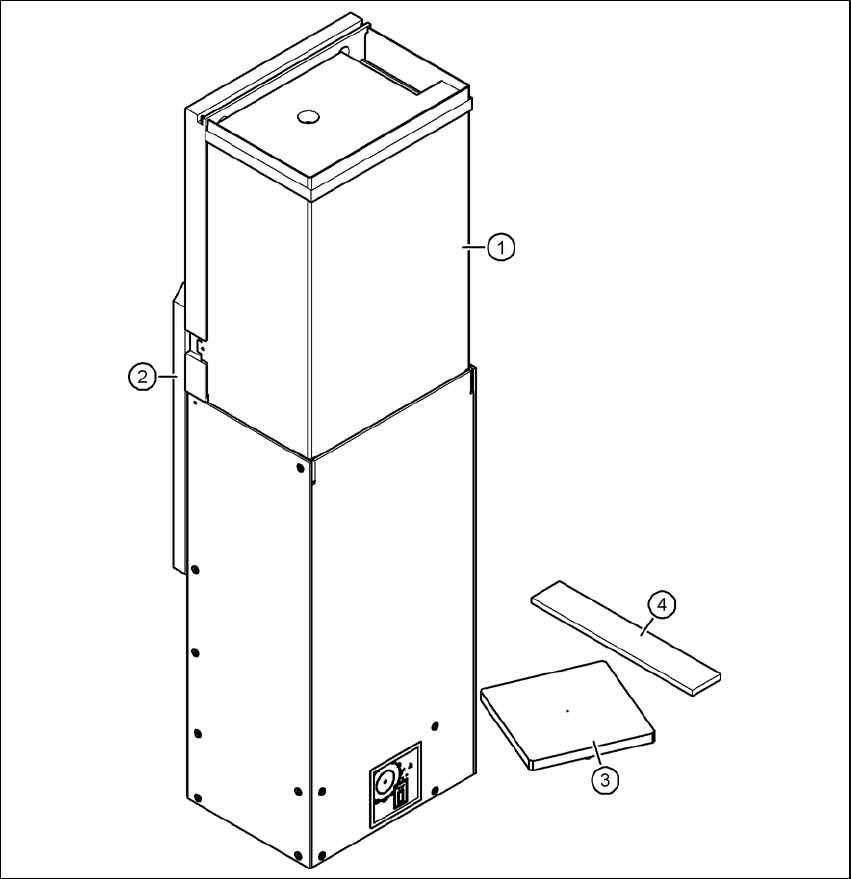
Fig. 3.2 - 8 Camera type 36 - parts
3
(1) Component camera, stationary, P&P, type 36, 32 x 32, digital, item no. 03042491-xx
(2) Mount for camera, type 33/36, item no. 03039467-xx
(3) Component support, camera type 25/33/36, complete, item no. 03039504-xx
(4) Focus point adjustment guide, camera type 33/36, item no. 03046391-xx
Cable set for vision teach station, stationary, item no. 03040355-xx