cab_products_electronic_industry.pdf - 第2页
2 Types De sig n and te chn ic al spe ci c ati on s corr es po nd to th e date of the pr in tin g. Su bje c t to chang e. Th e data pro vid ed in th e cata log do not re pr es ent any wa rr ant y or gua ra nte e. For cu…
Status: 07/2021
cab product overview
Devices and systems
for the electronics production
2
Types
Design and technical specications correspond to the date of the printing. Subject to change.
The data provided in the catalog do not represent any warranty or guarantee.
For current data see website www.cab.de/en/electronics
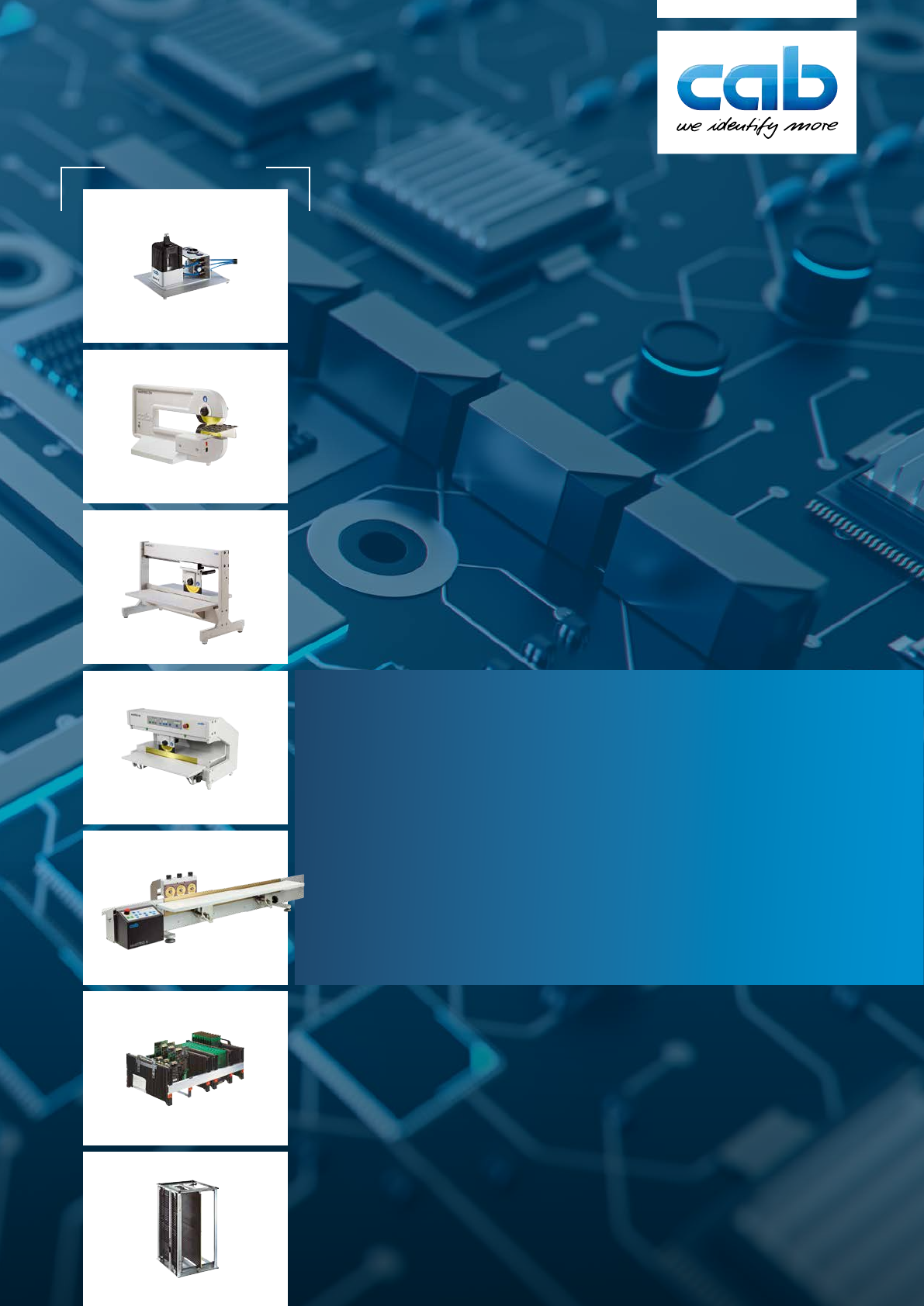
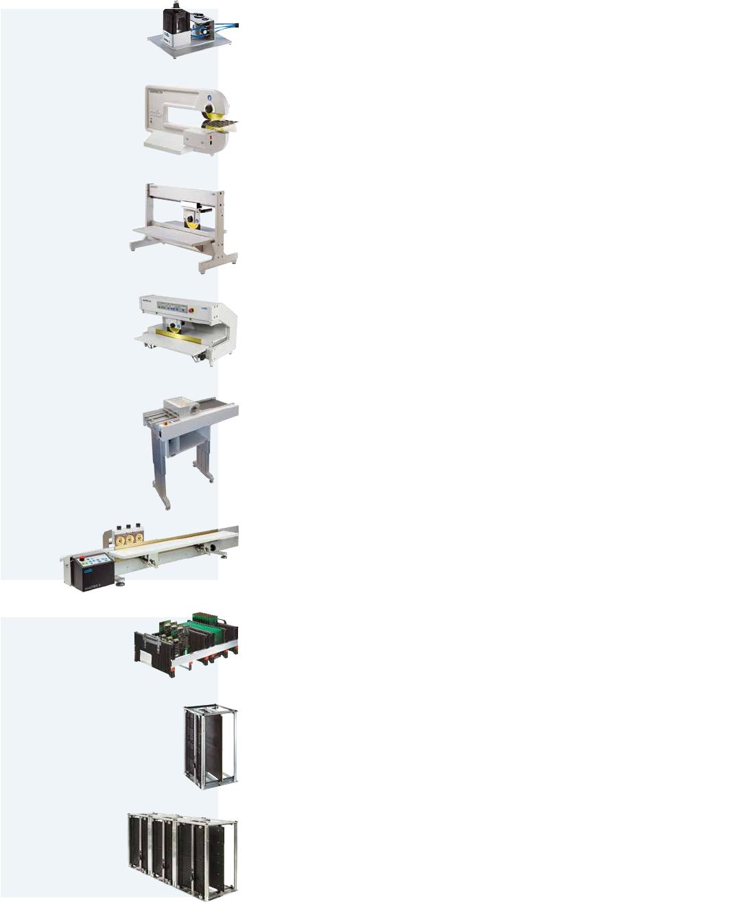
Off-cut remover HEKTOR 2
PCB separators MAESTRO 2, 2M
PCB separator MAESTRO 3E
PCB separator MAESTRO 4S
Conveyor belt
PCB separator MAESTRO 5L
PCB separator MAESTRO 6
PCB magazine series 100, 180, 300
PCB magazine series 600, 700, 800
PCB magazine accessories
Special magazines
Pages 9 - 11
Page 8
Pages 12 - 14
Page 4
Page 5
Pages 15 - 20
Pages 6/7
Page 21
Page 3
3
A
D
E E
2
F
G
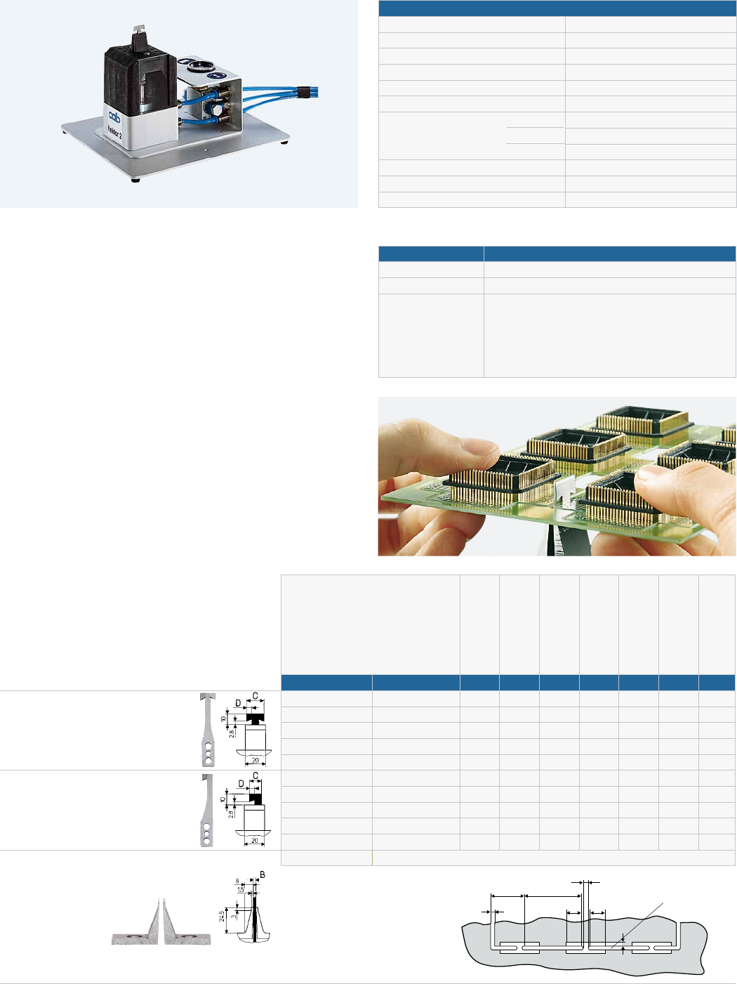
Off-cut remover HEKTOR 2
PCBs are separated carefully and quickly, o-cuts are removed
precisely and smoothly. A two-part matrix enables the dierent
blades to be assembled resp. exchanged easily.
O-cuts are punched out with the help of a compressed air cylinder.
The operating pressure can be set on the unit.
Safe operation
PCBs are positioned with their milled groove over the blade onto
the matrix. The o-cut is fed below the punch blade. A foot switch
triggers the punching and the o-cut is collected in the bottom tool.
Technical data
Separation method Punch blade
Operation manual
Material FR4
PCB thickness up to 2.5 mm
Air pressure supply 1/4“ coupling socket
Operating pressure, typical
4 bar
Temperature / Operation + 10 - 35°C / 10 - 85 %
humidity Stock 0 - 60°C / 20 - 80 %
not condensing Transport – 25 - 60°C / 20 - 80 %
Width x Height x Depth
220 x 170 x 255 mm
Weight 2.7 kg
Approvals CE, FCC Class A
Part no. Product
8932145 O-cut remover HEKTOR 2 (no blades)
8932xxx Blade (to be ordered separately)
Scope of delivery O-cut remover with pressure regulator
Foot switch
Allen key 2 mm
Allen key 4 mm
Operator's manual DE/EN
Blade
To prevent from getting stuck
in the PCB, the milled groove
should extend the blade width
by at least 0.15 mm.
Milled groove
width
Blade width
Blade length
Cutting length
Solder side free
of components
Milled groove
length
O-cut width
Part no. A B C D E F G
8932137.001 Blade 1,5 T ≥ 1.5 1.35 17.2 4.7 > 19 > 19 3
8932138.001 Blade 2,0 T ≥ 2.0 1.85 17.2 5.2 > 19 > 19 3
8932191.001 Blade 2,4 T ≥ 2.4 2.25 18 5.7 > 19 > 19 3
8932139.001 Blade 2,5 T ≥ 2.5 2.35 18 5.7 > 19 > 19 3
8932144.001 Blade 3,0 T ≥ 3.0 2.85 18 5.7 > 19 > 19 2.5
8932122.001 Blade 1,5 L ≥ 1.5 1.35 12 4.7 > 15 > 13 3
8932123.001 Blade 2,0 L ≥ 2.0 1.85 12 5.2 > 15 > 13 3
8932141.001 Blade 2,4 L ≥ 2.4 2.25 12 5.7 > 15 > 13 3
8932124.001 Blade 2,5 L ≥ 2.5 2.35 12 5.7 > 15 > 13 3
8932125.001 Blade 3,0 L ≥ 3.0 2.85 12 5.7 > 15 > 13 2.5
8932171.001 Matrix (as a spare part)
T blade
to punch out o-cuts
on the right and le margins.
Turning the PCB is not necessary
L blade
used with small distances
between the o-cuts
Matrix
included in the scope of delivery
PCB bottom side
free of components
Further blade thicknesses
on request