MYCRONIC mypro-a40sx 设备介绍.pdf - 第2页
Specifications MYPr o series A40S X™ SY STEM FEA TURES A40SX On -the -fl y mou nt ord er opti mizati on Vision auto teach wit h snap-t o -grid Autom atic illum inatio n setti ngs Intelligent feed er concept — Agilis Aut …
MYPro series A40SX
™
pick-and-place
Specifications
January 2025
Specifications MYPro series A40SX™
SYSTEM FEATURES
A40SX
On-the-fly mount order optimization
Vision autoteach with snap-to-grid
Automatic illumination settings
Intelligent feeder concept —Agilis
Automatic feeder and component recognition
On-the-fly feeder loading
Dynamic feeder positions
Automatic board stretch compensation
Automatic conveyor width adjustment
Intelligent surface impact control
Tool collision avoidance
Multi-user, multi-tasking system software
Open software interfaces for factory integration
SQL database engine
Hermes
COMPONENT RANGE
HIGH PRECISION MOUNTHEAD — MIDAS
Component specification
Min: 0.3 x 0.15 (0.012 x 0.006”) (03015)
Max: 99 x 73 x 22 mm (3.89 x 2.87 x 0.0,86”)
(1) (3)
Max: component weight: 140 g
(2)
(1) With 4K vision. Max component size with 2K vision: 99 x 56 x 22 mm (3.89 x 2.20 x 0.86”).
(2) Depending on mounthead, mount tool, package, and production altitude.
(3) Components with diagonal larger than 58 mm must be presented in the same angle as placed.
HIGH SPEED MOUNTHEAD — MX7
Component specification
Min: 0.4 x 0.2 mm (0.016 x 0.008”) (01005)
Max: 45 x 45 x 15 mm (1.77 x 1.77 x 0.59”)
(1)
Max: 150 x 40 x 15mm (5.90 x 1.57 x 0.59”)
(1)
(1) Components with diagonal larger than 52mm will if needed be rotated over the place area
ELECTRICAL VERIFIER (OPTIONAL)
Component range
Resistor, capacitor, unipolar capacitor, diode (forward voltage,
reverse current), Zener diode (reverse voltage), bipolar transistor
(current gain), FET/IGBT (gate threshold voltage). Smallest chip size
1.0x0.5 mm (0.04x0.02”).
PLACEMENT SPEED AND ACCURACY
A40SX-13/17
Rated speed
(1)
29,000 CPH
IPC 9850 chip net throughput
(2, 3)
22,000 CPH
IPC 9850 chip throughput
(3)
23,000 CPH
IPC 9850 chip repeatability 3 σ (X, Y, Theta)
(7, 8)
30 µm, 1.8°
(6)
45 µm, 1.8°
IPC 9850 QFP repeatability 3 σ (X, Y, Theta)
(4)
21µm, 0.054°
(9)
30 µm, 0.12°
(6, 8)
45µm, 0.21°
(8)
IPC 9850 QFP accuracy @ Cpk 1.33 (X, Y, Theta)
(4, 5 )
35 µm, 0.09°
(9)
50 µm, 0.2°
(6, 8)
75 µm, 0.35°
(8)
The above specification achieved with a machine configuration including high precision mounthead (Midas),
high speed mounthead (MX7 ), line scan vision system (LVS), inline conveyor T460 and 22 mm component
max height. The IPC 9850 net throughput and accuracy numbers are obtained simultaneously, with the same
machine settings. The rated speed value is obtained under conditions optimized for speed.
(1) Depending on component and application.
(2) According to IPC 9850. Net throughput = (no of parts x 3,600)/(board build time + board transfer time).
(3) According to IPC 9850 0402C verification panel.
(4) According to IPC 9850 QFP64 / QFP100 verification panel.
(5) According to IPC 9850 Cpk 1.33 = 4 σ + offset.
(6) High precision setting, recommended for small chip or fine pitch.
(7) IPC 9850 chip accuracy @ Cpk 1.33, Theta = 2.6°
(8) High-speed mounthead - MX7
(9) High-precision mounthead - MIDAS
FEEDER CAPACITY
8 MM TAPE T460 T640
A40SX-13 160 144
A40SX-17 224 208
BOARD HANDLING
INLINE CONVEYOR T460 T640
Maximum board size
460 x 510 mm (18 x 20”) 640 x 510 mm (25 x 20”)
Minimum board size
(1)
70 x 50 mm (2.7 x 2”) 70 x 50 mm (2.7 x 2”)
Maximum board train length
436 mm (17.1”) 472 mm (18.5”)
Board thickness range
0.4–6.0 mm (0.016–0.24”) 0.4–6.0 mm (0.016–0.24”)
Board edge clearance top
3.2 mm (0.13”) 3.2 mm (0.13”)
Board edge clearance bottom
(2)
3.2 mm (0.13”) 3.2 mm (0.13”)
Top side clearance (max) 22mm (0.86”) 22mm (0.86”)
Bottom side clearance (max)
(3)
32 mm (1.25”) 32 mm (1.25”)
Maximum board weight 4 kg (8.8 lbs) 4 kg (8.8 lbs)
Board transfer height
Conforms to SMEMA standard for board transfer height.
Height adjustable from 880 to 975 mm (34.6 to 38.4”).
Operation mode Inline, manual, inline odd-board, left-to-right/right-to-left.
(1) Board train specification: 90 x 50 mm (3.5 x 2”) board size, 1.6 mm (0.06”) min thickness. Max warpage 1 mm (0.04”).
(2) Edge clearance 5.5 mm (0.22”) if component taller than 6 mm (0.24”). 14.3 mm (0.56”) if taller than 19 mm (0.75”).
(3) 15 mm (0.59”) with support pins.
VISION CAPABILITY
LINESCAN VISION SYSTEM — 4K RESOLUTION
Component type Field of View Minimum pitch Minimum lead width
Leaded components
80 mm (3.1”)
0.10 mm (4 mil) 0.05 mm (2 mil)
Bumped components
80 mm (3.1”)
0.15 mm (6 mil) 0.08 mm (3 mil)
LINESCAN VISION SYSTEM —2K RESOLUTION
Component type Field of View Minimum pitch Minimum lead width
Leaded components
63 mm (2.5”)
0.20 mm (8 mil) 0.10 mm (4 mil)
Bumped components
63 mm (2.5”)
0.25 mm (10 mil) 0.13 mm (5 mil)
4086744 REV 0002 / JANUARY 2025
MYCRONIC.COM
SWEDEN
Mycronic AB
PO Box 3141
Nytorpsvägen 9
SE-183 03 Täby
Tel: +46 8 638 52 00
GERMANY
Mycronic GmbH
Tel: +49 89 45 24 24 8-0
UK
Mycronic Ltd.
Tel: +44 1202 723 585
FRANCE
Mycronic S.A.S.
Tel: +33 1 41 80 15 80
NETHERLANDS
Mycronic B .V.
Tel: +31 402 62 06 67
USA
Mycronic Inc.
Tel: +1 978 495 9799
SOUTH KOREA
Mycronic Co. Ltd.
Tel: +82 31 387 5111
CHINA
Mycronic Co., Ltd.
Tel: +86 21 3252 3785 / 86
SINGAPORE
Mycronic Pte Ltd.
Tel: +65 6281 7997
JAPAN
Mycronic Technologies
Corporation
Tel: +81 42 433 9400
Specifications are subject to change without notice. Mycronic, MYDATA, MYDATA automation and MY; Mycronic 4.0; MYNews; MYCare; MYSynergy, MYTrilogy; MYPro, MYPro Line; MY100, MY100e, MY200, MY300, MY300DX, MY300EX,
MY300HX, MY300LX, MY300SX, MY500, MY600, MY700, MY700JD, MY700JP, MY700JX; MYPro A40, A40DX, A40SX, A40LX; MYPro S20; MYPro S30; MYPro I50, I51, I80, I81, I90, I91; MYSmart, MYC10, MYC50, MYC60, MYD10, MYD50, MYT10, MYT50;
Mycronic SMD Tower; MYTower 5, 6, 6+, 7+, 5x, 6x; Vi TECHNOLOGY, VIT; 5K, 5K3D, 8K, 8K3D, 9K, 9K3D; PI, PI Pico, PI Primo; SIGMA Link; MX7, HYDRA, Midas, ISIC; Agilis, Agilis Linear Magazine (ALM), Agilis Linear Magazine Flex (ALM FLEX), Agilis
Stick Magazine(ASM), Agilis TrayMagazine(ATM); Mycronic Tray Exchanger (TEX), Mycronic Tray Wagon Magazine (TWM); Mycronic Dip Unit (DPU); Mycronic Linescan Vision System (LVS); Mycronic Assembly Process Management (APM)
including; JPSys, STSys, TPSys, MYCam, MYCenter, MYCenterAnalysis, MYLabel, MYPlan, MYPro Connect, MYPro Link, MYTrace and FlowLine are registered trademarks or trademarks of Mycronic AB. Mycronic AB is ISO 9001:2015 and ISO 14001:2015 certified.
SOFTWARE
SOFTWARE MODULES (OPTIONAL)
Shared databases
Line mode
PCB ID (2D barcode)
Pre-pick inspection
Barcode software
PRM (Proactive Replenishment Monitoring) software
Hermes
OFFLINE SOFTWARE TOOLS (OPTIONAL)
Data preparation — MYCenter
Optimization and scheduling — MYPlan
Inventory management and kitting — MYCenter
Traceability — MYTrace
Performance monitoring — MYCenter Analysis
MISCELLANEOUS
INSTALLATION REQUIREMENTS
Power requirements
Three phase AC 6.6 kVA
(3 x 2.2 kVA)
Power consumption 1.5 kW (average)
Voltages
3 x 200, 210, 220, 230, 240,
250 ± 10 %, Y or Delta
Air supply No air required
Air temperature + 18 to + 35 °C (65 to 95 °F)
Air humidity < 95 % RH non condensing
MACHINE WEIGHT
(1)
A40SX-13 1,600 kg (3,500 lbs)
A40SX-17 2,200 kg (4,850 lbs)
(1) Total machine weight excluding magazines.
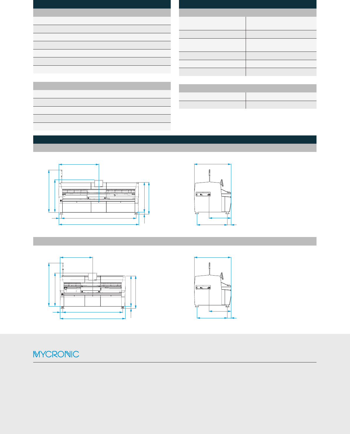
DIMENSIONS [ mm ]
A40SX-17
1632
980
±5
1346
167
1,765
1,867
1,325
1,406
81.5
1,438
3,304113
3,530
2082
1883
1339
1041
1,404.5
1,867
1,325
1,406
81.5
1,438
2,584
113
2,809
1,632
980±5
1,346
167
2082
1883
1339
1041
1,404.5
1,867
1,325
1,406
81.5
1,438
2,584
113
2,809
1,632
980±5
1,346
167
A40SX-13
2082
1883
1339
1041
1,404.5
1,867
1,325
1,406
81.5
1,438
2,584
113
2,809
1,632
980±5
1,346
167