Infinity EX Camera System Module.pdf - 第2页
INFINITY EX CAME RA SY STEM MO DULE MODULE OVE RVIEW 17.2 Technical Reference Manu al Chapter Issu e 3 Jan 04 is home (raised) the LED is on as the beam is broken by the v ane. Figur e 17-1 Camera and V ision System Ov e…

INFINITY
EX
CAMERA SYSTEM MODULE
MODULE OVERVIEW
Chapter Issue 3 Jan 04 Technical Reference Manual 17.1
CHAPTER 17 CAMERA SYSTEM MODULE
MODULE OVERVIEW
Purpose The camera and vision system is the mechanism which positions a camera and
board stop assembly to perform the following tasks:
• Board Stop
• Fiducial Capture
• 2D Inspection Site Capture
• Under Screen Cleaner Drive
• Board / Screen Inspection
Elements The main camera and vision elements are:
• Board Stop Mechanism
• X Axis Drive Mechanism
• Y Axis Drive Mechanism
• Green CCD Camera Unit/Optics/Lighting Unit
• Gold CCD Cameras/Optics/Lighting Unit (optional)
Operation The green camera is a standard CCD unit fitted with a special optics/lighting
unit. The split optics unit allows the camera to view both the board and screen
at the same time. The image data is processed by a single vision card located
within the machine PC and displayed in a combined vision window on the MMI.
The optional gold camera consists of two standard CCD camera units within a
special optics/lighting unit. The cameras are synchronised allowing for simuta-
neous capture of both board and screen images. The image data from each
camera is processed by individual vision cards located within the machine PC
and displayed in separate vision windows on the MMI.
The software controlled lighting unit, includes rings of LEDs to allow precise
control over board and screen illumination during fiducial and 2D camera
capture operations.
Positioning of the camera is carried out by the X and Y drive mechanisms which
use two servo motors and encoders driven by the servo drive cards in the
machine controller enclosure.
The board stop is a pneumatically driven unit which is lowered to stop the board
in position ready for clamping and vision alignment to take place. The board
stop solenoids are energized by 24V, from MultiMove X13 source 4.
The board at stop diffuse background suppressed opto detects the board when it
reaches the board stop. The sensor has a red LED along with a sensitivity
control. As a board approaches the stop it is detected by the sensor (the sensor
element faces downwards) and the red LED lights. This starts a timer which
when elapsed stops the belts and clamps the board.
The board stop in, through beam opto is fitted to ensure that the board stop is
raised before any camera carriage movement is demanded.
This board stop in sensor is mounted on the camera carriage and has an LED
mounted in its body which illuminates when the beam is broken. When the stop
INFINITY
EX
CAMERA SYSTEM MODULE
MODULE OVERVIEW
17.2 Technical Reference Manual Chapter Issue 3 Jan 04
is home (raised) the LED is on as the beam is broken by the vane.
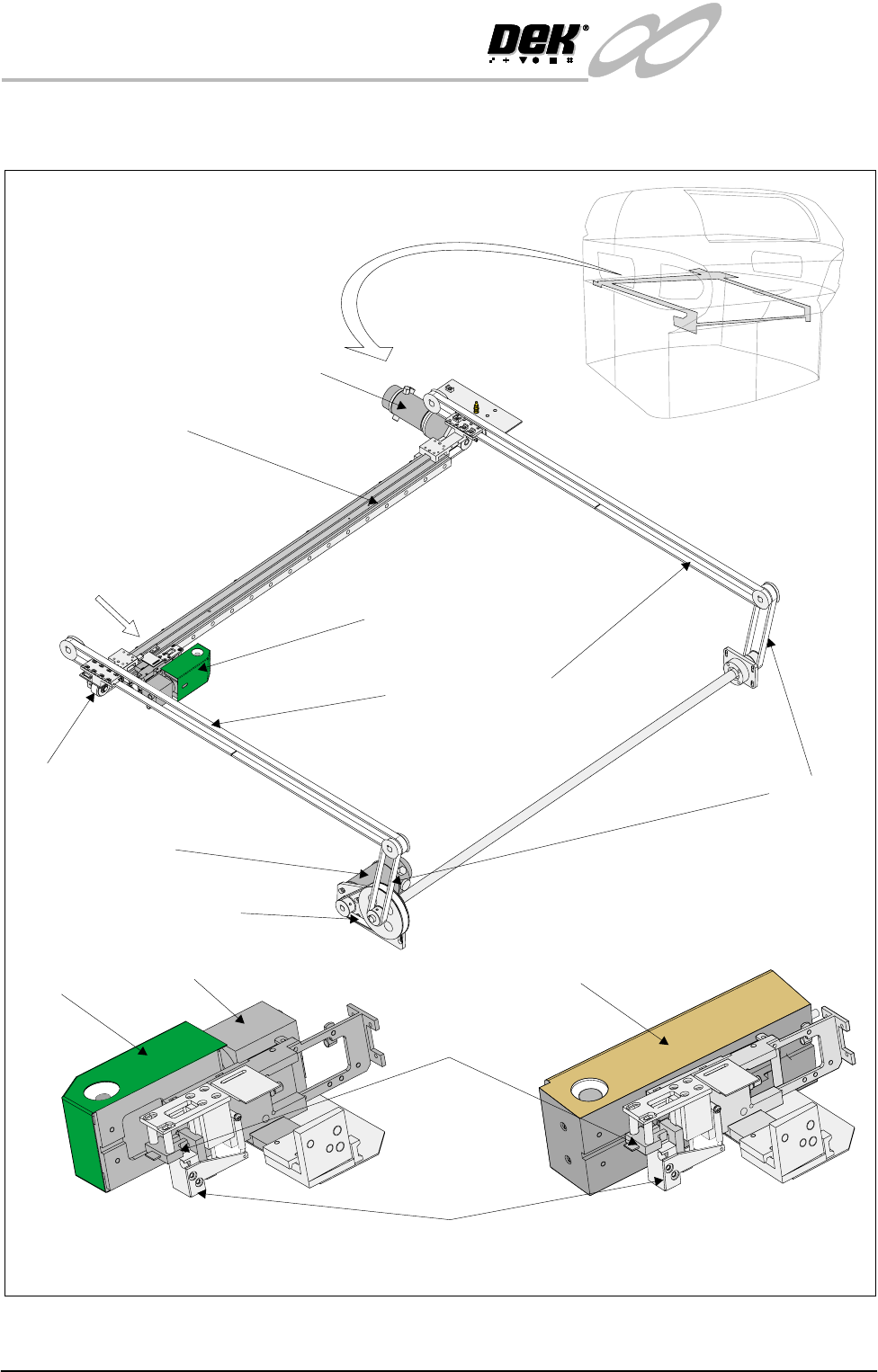
Figure 17-1 Camera and Vision System Overview
View on Arrow A
Green Camera
Gold Camera
Optical Unit
GreenCamera
Gold Cameras & Optical Unit
BoardStop
BoardStopIn
Sensor
Main Y Axis Timing Belts
X Axis Timing Belt
Camera X Motor
Camera Carriage
Camera Assembly
Y Transfer
Timing Belts
Camera Y Motor
Y Motor Timing Belt
A
INFINITY
EX
CAMERA SYSTEM MODULE
ELECTRICAL SCHEMATIC
Chapter Issue 3 Jan 04 Technical Reference Manual 17.3
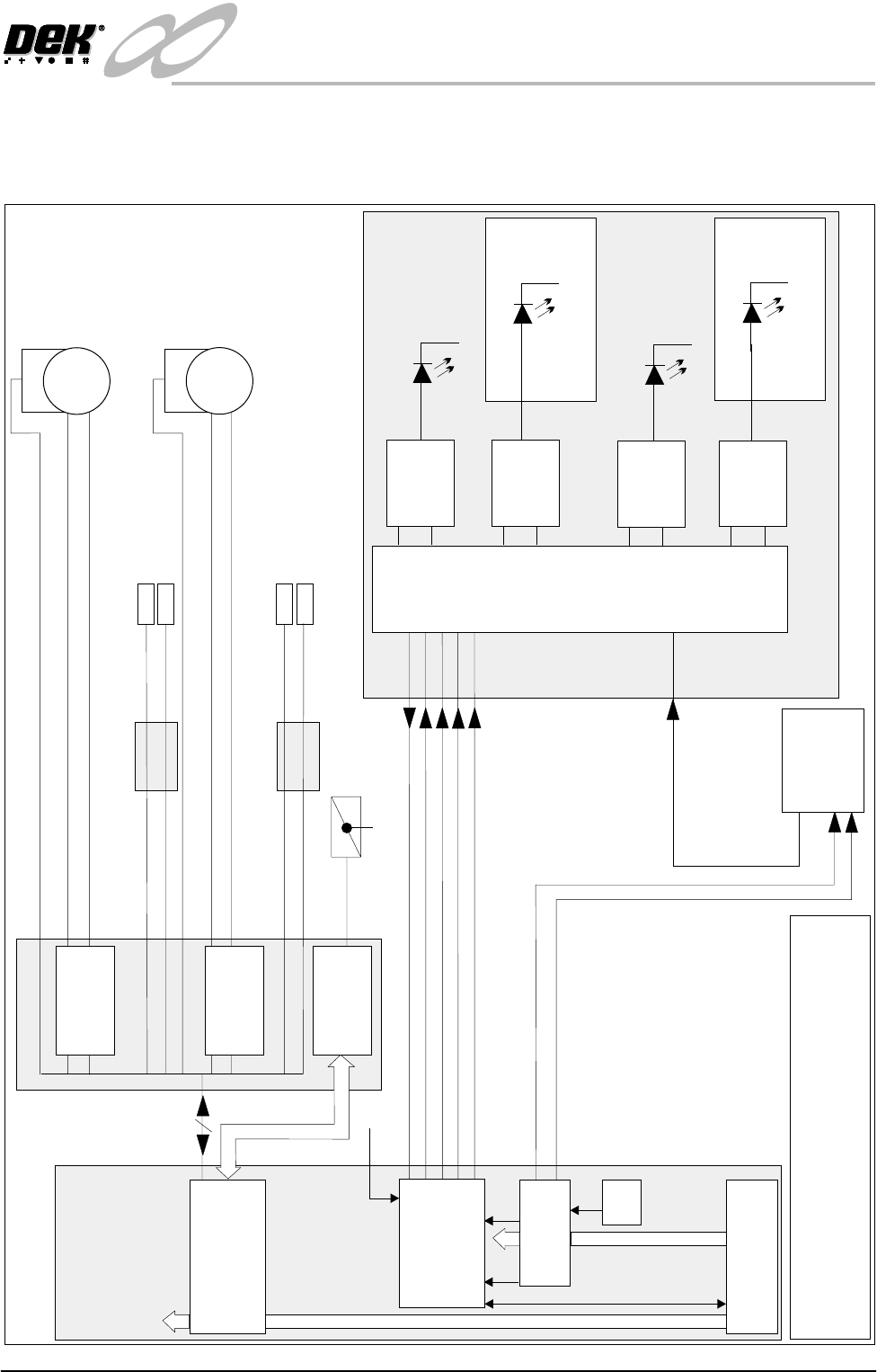
ELECTRICAL SCHEMATIC
Green Camera
Y Camera Motor
Encoder
Servo
Motor
Encoder
Servo
Motor
X Camera Motor
+
_
+
_
SOURCE 4
Board Stop
Manual Operation
Optical Unit
Video
+12V
Camera
Video
Screen Direct
LEDs
24V
Constant
Current
Generator
Board Direct
LEDs
24V
Constant
Current
Generator
Constant
Current
Generator
Constant
Current
Generator
Screen Oblique LEDs
24V
Upper Lighting Board
Board Oblique LEDs
24V
Lower Lighting Board
Strobe
RX
0V
TX
24V U/S
Processor
NOTE
The CAN Bus forms part of the 100 way connection
between the Machine PC and Controller enclosures
100 Way
RS232
Strobe
Trig
NextMove
Processor
Cognex
I
S
A
B
u
s
P
C
I
B
u
s
+12V
PSU
Vision PC
Adaptor
Machine PC
Breakout
Board A
X Home Sensor
Y Home Sensor
DIG IN 15
DIG IN 5
MultiMove1
X13
Servo Drive
X8
Servo Drive
X10
Board Stop In (Up)
Board At Stop
DIG IN 23
DIG IN 22
Breakout
Board B
Machine Controller
CAN Bus
+24V (US)