ASM贴片机SX2机型电路图.pdf - 第30页
electric_schematic_SX12_V3 90013315-010101LE3 Replaced by Block_diagram Gantry2 Replaced by Weitergabe sowie Vervielfältigung dieser Unterlage, Verwertung und Mitteilung des Inhalts nicht gestattet, soweit nicht ausdrück…
electric_schematic_SX12_V3
90013315-010101LE3
Replaced by
Block_diagram Gantry1
Replaced by
Weitergabe sowie Vervielfältigung dieser Unterlage, Verwertung und
Mitteilung des Inhalts nicht gestattet, soweit nicht ausdrücklich zugestanden.
Proprietary Data, company confidential.
All rights reserved
Copying of this document, giving it to others and the use or
communication of the contents thereof, are forbidden without express authority.
Doc. No.
00 01 02 03 04 05 06 07 08 09
Privileged business information.
Do not release
Offenders are liable to payment of damages. All rights are reserved in the
event of the grant or the registration of a utility model or design.
Zuwiederhandlungen verpflichten zu Schadenersatz. Alle Rechte vorbehalten,
insbesondere für den Fall der Patenterteilung oder GM-Eintragung vorbehalten.
Page:
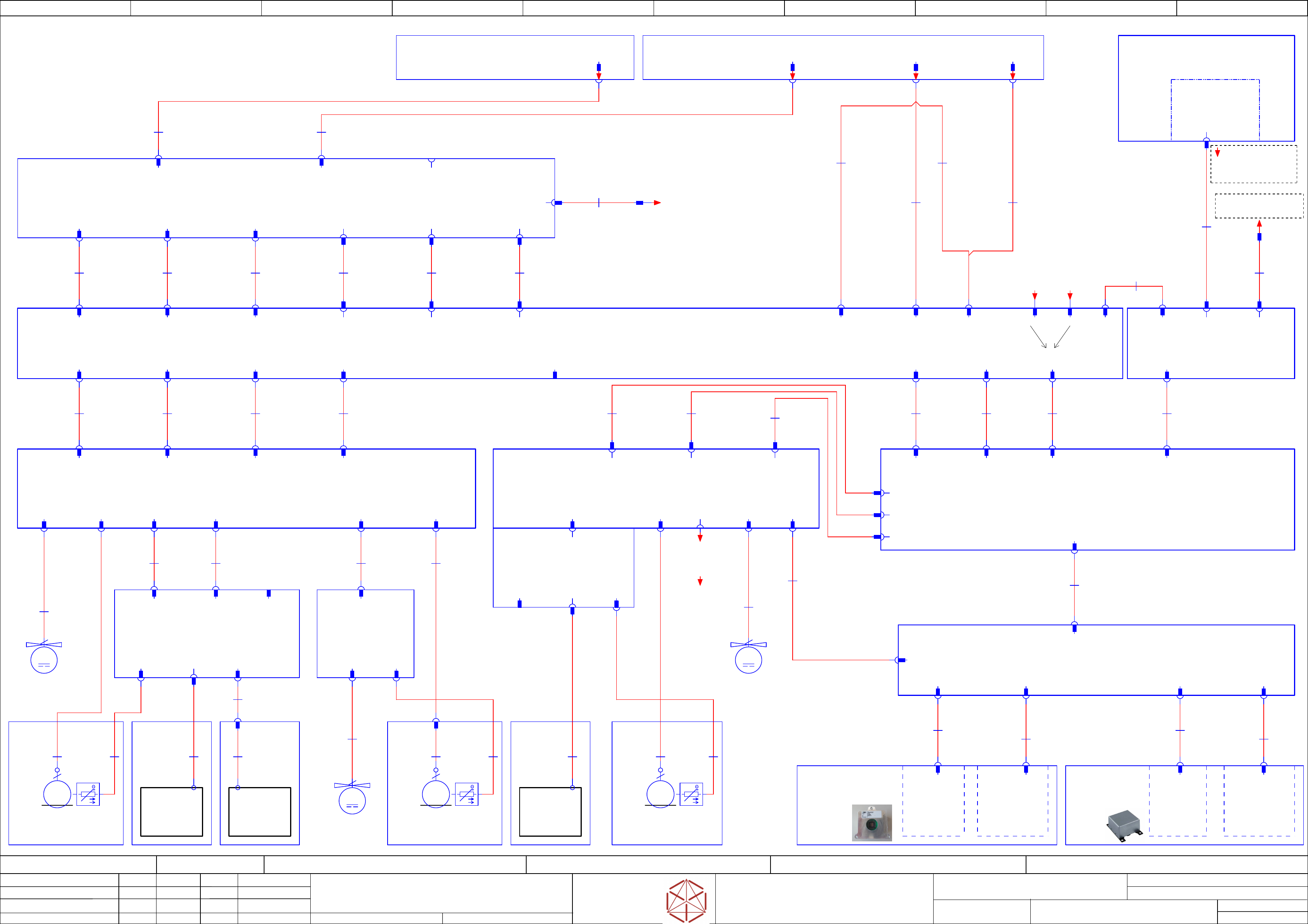
Function: Overview
==OV=SX12_V3+GA/24
drawing number:
03055284-030401LE3
Gantry_1
GmbH & Co KG
ASM
Assembly Systems
Copyright reserved
Ed.
Original
Langerd
Date
Date
Modification
Appr
05.05.2020
Name
starting MC-Nr.: 2018/Q3 G. Pingist
Size DIN A2
Sheet
24
/
3
Gantry 1
MCAN & GCAN
signals to X7
-MY1
Fan Y1 motor
03085456
==GA+GA1/82.00
M
2
-MY2
Fan Y2 motor
03085456
==GA+GA1/82.09
M
2
-MX
Fan X motor
03085456
==GA+GA1/84.06
M
2
3~
3+PE
M
-aa
Trailing-Interface SX1/2 (GigE)
03215039
==CH/62.00
-ag
Vision Base Interface VBI
03100950
==CH/63.07
-aq
Gantry-Interface Y SX1/2 (GigE)
03215037
==GA+GA1/82.00
-X1
Trailing cable Y1
Y1_MOTOR
-X2
Trailing cable Y2
Y1_MOTOR
-X1aq
Flat rib. cable
34x0,14
03204801
-W1
Trailing-cable_Y1_(GigE)
Y1_Motor
Flat rib. cable
34x0,14
03204802
-W1
Trailing_cable_Y2_(GigE)
Y1_Motor
-ac
PCBA Head interface C700B V2
03214132
==GA+GA1/84.00
-X12
X-Motor
-X11
Base adapter
-au
Vision Head Interface VHI
03100949
==GA+GA1/85.00
-X.J5
-X1aa -X2aa
-X2aq
-X3
Trailing cable Y3
Y2_MOTOR
-X4
Trailing cable Y4
Y2_MOTOR
-X3aq
Flat rib. cable
34x0,14
03204803
-W1
Trailing_cable_Y3_(GigE)
Y2_Motor
Flat rib. cable
34x0,14
03204804
-W1
Trailing_cable_Y4_(GigE)
Y2_Motor
-X3aa -X4aa
-X4aq
-X7
Trailing cable Y7
Head-Communication
Flat rib. cable
34x0,14
03204807
-W1
Trailing_cable_Y7_(GigE)
Head-Com.
-X7aa
-X3an
-X5
Motor/Power
Y1-Axis
Cable: Camera type 41 GigE
03112087
-1W1
-X.J14
CAM 1
-X14.VHI
-X1.CAM
-CAM1
GXS50 GigE CMOS
5Mpix Kamera
BAUMER
03101676
-A1
PCBA
Vision LED controller
VLC48 GigE
03146613
Cable VHI - VLC41 GigE
03112088
-1W1
-X9.VHI
-X1.VLC
-X.J9
CAM 1
Cable Camera Type 34 GigE
03090967
-2W1
-X1.CAM
-CAM2
GXS03 GigE
CCD VGA camera
BAUMER
03101431
-A2
PCBA
Vision LED controller
VLC34 GigE
03100758
-PCB_Cam
PCB camera
(Type 34) 28 GigE
03101402
==GA+GA1/85.05
Cable VHI - VLC34 GigE
03097629
-2W1
-X1.VHI
-X1.VLC
-X16.VHI
-X.J16
CAM 2
-X.J1
CAM 2
-Co_Cam
Component Camera C+P
(Type 48) 8x8 GigE
03131695
==GA+GA1/85.00
-MY1
Linear motor
Y1 axis
03092337
==GA+GA1/82.00
0305196003051960
-X1
Trailing cable Y1
Motor Y1
-X2
Trailing cable Y2
Motor Y1
-X3
Trailing cable Y3
Motor Y2
-X4
Trailing cable Y4
Motor Y2
-FD.A1
Fuse and distribution
03104070
==PS002+/44.00
-PC
Control computer BoxPC-427D i3 2xPCIe
03114177
==CH+CTRL/58.00
-X.J3
PC
-X1.GigE
-J3.VBI1
CAT.6A S-FTP RD
8x0,14
03221650
-W1
Cable: VBI 1 camera bus GigE
FT
-X1
GigE 1
-X17
MCAN1
-X18
GCAN
-an
Gantry-Interface X SX1/2 (GigE)
03215041
==GA+GA1/83.00
-XB8a
-XB8aqy
-XB1a
-XB1aqy
-X15aa
-X15
POWER 160V / 42V
Gantry 1
supply 24V
150V & Signals
03068132
-W1.1
-X13aa
-X13
P27V
PWR_OK
PWR_ENA
Gantry 1 supply
40V/160V & Signals
03068132
-W1.2
-X14aa
-X14
POWER
VISION
Powerfail, DC 24V
03068132
-W1.3
Camera Illumination
03068132
-W1.4
-XB5a
-XB5aqy-X21.CSB
24V, Power fail
03112207
-W1
-X1sp-X2sp
Main axis voltages gantry 1
03112206
-W1
03085456
-W1.1
-X10
FAN X/Y Motor
-X10aq
-cb
Sensor module Y axis
03064608
==GA+GA2/86.01
-X2
-X7
Sensor module
Y axis
-X7aq
-X9
Temp.
sensor
-X9aq
-X21ab
-X21
temp & fan
03052148
-W1
-X12ab
-X12
Temp. sensor
03052145
-W1
-X31
Debug-connector
-X11
Temp
-X1
-X1
Read head 1
-X2
Read head 2
-X2ab
03052657
-W1
-UY1
Read head MS20
Y1 axis
03052657
==GA+GA1/84.03
Read head cable
03052657
-W1
-UY2
Read head MS20
Y2 axis
03052657
==GA+GA1/84.07
-X2ab2
Read head cable
03052144
-W1
-X8
Temp & fan
-X6
Motor/Power
Y2-Axis
-X1ar
temp & fan
03052147
-W1
Motor Y2 axis
03052146
-W1
-X8aq -X6aq
-X6aq2
-X1
Temp & fan
-X2
-ar
Sensor interface
03060962
==GA+GA1/82.07
Fan Y2-Motor
03085456
-2W1
-X3
FAN Y2 Motor
-X3ar
3~
3+PE
M
-MY2
Linear motor
Y2 axis
03092337
==GA+GA1/82.06
0305196003051960
-X1
-X2
Temp
-X6
Trailing cable Y6
Head-Power
-X5
Trailing cable Y5
X Motor
-X2an
Flat rib. cable
34x0,14
03204806
-W1
Trailing_cable_Y6_(GigE)
Head-Power
Flat rib. cable
34x0,14
03204805
-W1
Trailing_cable_Y5_(GigE)
X-Motor
-X6aa-X5aa
-X1an
-X2
Trailing cable Y6
Head-Power
-X1
Trailing cable Y5
Motor X
-X16
POWER VBI
-ak
Sensor module X axis
03068500
==GA+GA1/84.00
-X15
Sensor module
-X21
-X31
Debug
connector
-X11
Temp
03066858
-UX
Read head MS20
X axis
03066858
==GA+GA1/84.01
-X1
Read head
-X2
3~
3+PE
M
-MX
Linear motor
X axis
03092336
==GA+GA1/84.03
0307249803072498
-X1
UL1007
2x0,2
03085456
-3W1
Fan
Y2-Motor
-X8
40V Fan
-X8ac
-X14
Signal Vision
-X14ac
-X.J5au
SFSD-08-28-H-04.00-DR-NDX
16x0,08
03112169
-W1
Cable: Head interface - VHI
Flat rib. cable
34x0,14
03204814
-W1
Trailing_cable_X4_(GigE)
GigE
-X.J11
-X8an
-X.J11au
-X8
Trailing cable X3
GigE
Flat rib. cable
34x0,14
03204811
-W1
Trailing_cable_X1_(GigE)
X-Motor
Flat rib. cable
34x0,14
03204812
-W1
Trailing_cable_X2_(GigE)
Head-Power
-X5 Trailing cable X1
Motor X
-X6 Trailing cable X2
Head-Power
-X5
Trailing cable X1
X-Motor
-X6
Trailing cable X2
Head-Power
-X5ac -X6ac
-X5an
-X6an
-A2
Safety breaker unit
PCB Pre-/discharge assembly
03108631
==CSB+/46.00
-X21
-X10aa -X11aa
-X20aa
-X3sp -X4sp
-MGCU1
Gantry 1
Position controller gantry axis MGCU-3
03103477
==CH/62.00
-X3sp
Power
Y1 motor
-X4sp
Power
Y2 motor
-X74Usc
MGCU1 - MGCU2 bus
-X74Usc -X74Uuc
MGCU1 - MGCU2 bus
03055207
-W1
X motor gantry 1
03112225
-W1
-X6sp
-X12aa
Sensor bus X
03055260
-W1
Y1 motor gantry 1
03112220
-W1
Y2 motor gantry 1
03112221
-W1
Sensor bus Y
03055276
-W1
RT-HCU bus
03055275
-W1
-X6sp
Power
X motor
-X73Osc
RT-HCU bus
-X72Usc
Sensor bus Y
-X22aa
-X73Usc
Sensor bus X
-X10
Y1_MOTOR
-X11
Y2_MOTOR
-X21
Sensor bus Y
-X20
HCU bus
-X12
X_MOTOR
-X22
Sensor bus X
-X2sp
DCLV 260V
-X1sp
Supply 24V
-X21aa
-X73Usc-X72Usc-X73Osc
-X72Osc
Diagnose
-X7an
-X7 Trailing cable X3
Head-Communication
-X.J11
Trailing cable GigE
Flat rib. cable
34x0,14
03204808
-W1
Trailing_cable_Y8_(GigE)
GigE
-X.J11ag
-X4an
-X7ac
-X7
Trailing cable X3
Head-Communication
Flat rib. cable
34x0,14
03204813
-W1
Trailing_cable_X3_(GigE)
Head-Com.
-PC.GigE
GigE Ethernet Adapter dual-Port
PCI-E I350T2BLK
03115569
-X.J8
CAM1
-X.J6
P27V
-X16
POWER VBI
-X16.TI -J6.VBI
Single core
2x0,5
03223180
-W1
Cable: Power VBI
-X22.1_IC1
CAT.6A S-FTP RD
03221649
-W1
Cable: Stat. cameras 1
camera bus GigE
-J8.VBI1
-X3
Trailing cable Y7
Head-Communication
-X4
Trailing cable Y8
GigE
==HD1+-X3.CP20
Head-interface
to X-Base-adapter
+HD/27.04
==GA1+-MCAN
+CH/13.00
==GA1+-GCAN
+CH/13.01
+PS002/10.06
-DC160V_GA1
+PS002/10.03
-supply_GA1
+PS002/10.04
-Control_GCU1_2
+PS002/10.08
-MGCU1&2_300V
+-MGCU1-MGCU2
==CH-MGCU2-X74Uuc /25.04
==stCAM+Loc1-CAN.VLC25
Stationary camera
+stCAM/14.00
==GA=+-VBI.1
Control Computer
==CH+CTRL-PC.GigE-X1 +CH/11.01
==HD1+-X3.CPP
Head-interface
to X-Base-adapter
+HD/28.05
electric_schematic_SX12_V3
90013315-010101LE3
Replaced by
Block_diagram Gantry2
Replaced by
Weitergabe sowie Vervielfältigung dieser Unterlage, Verwertung und
Mitteilung des Inhalts nicht gestattet, soweit nicht ausdrücklich zugestanden.
Proprietary Data, company confidential.
All rights reserved
Copying of this document, giving it to others and the use or
communication of the contents thereof, are forbidden without express authority.
Doc. No.
00 01 02 03 04 05 06 07 08 09
Privileged business information.
Do not release
Offenders are liable to payment of damages. All rights are reserved in the
event of the grant or the registration of a utility model or design.
Zuwiederhandlungen verpflichten zu Schadenersatz. Alle Rechte vorbehalten,
insbesondere für den Fall der Patenterteilung oder GM-Eintragung vorbehalten.
Page:
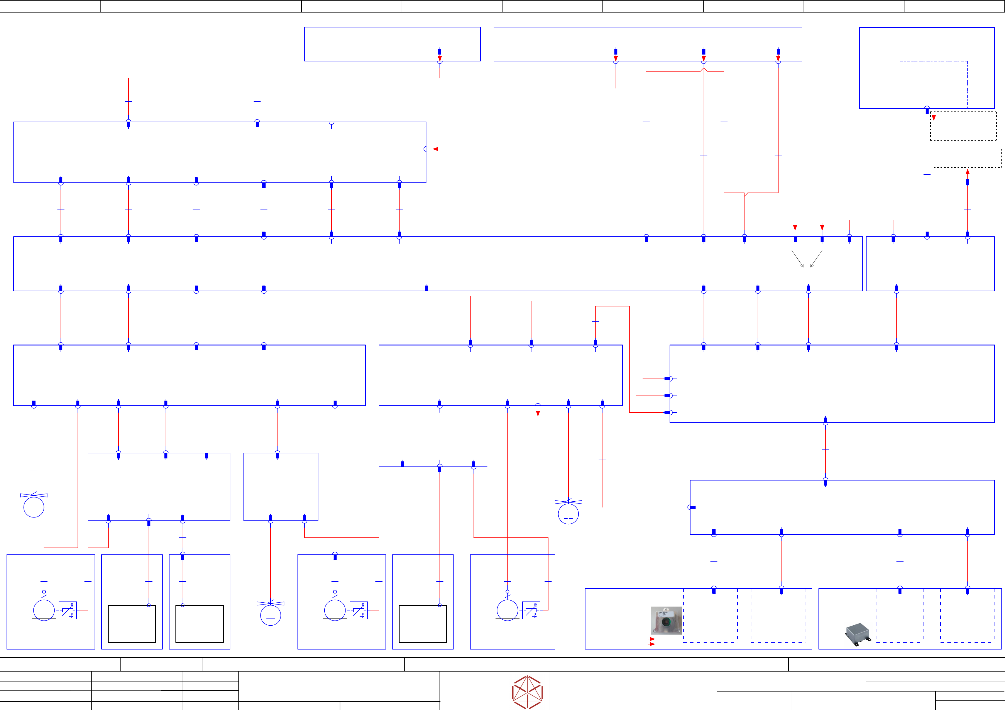
Function: Overview
==OV=SX12_V3+GA/25
drawing number:
03055284-030401LE3
Gantry_2
GmbH & Co KG
ASM
Assembly Systems
Copyright reserved
Ed.
Original
Langerd
Date
Date
Modification
Appr
14.05.2020
Name
starting MC-Nr.: 2018/Q3 G. Pingist
Size DIN A2
Sheet
25
/
3
-MY1
Fan Y1 motor
03085456
==GA+GA2/86.00
M
2
-MY2
Fan Y2 motor
03085456
==GA+GA2/86.09
M
2
-MX
Fan X motor
03085456
==GA+GA2/88.06
M
2
MCAN & GCAN
signals to X7
Gantry 2
Interface
Data
3~
3+PE
M
Cable: Camera Type 30 GigE
03106502
-1W1
-X14.VHI
-X1.CAM
-CAM1
GXS50 GigE
CMOS 5MPix camera
BAUMER
03101676
-A1
PCBA
Vision LED controller
VLC30 GigE
03102790
Cable: VHI - VLC30 GigE
03106511
-1W1
-X9.VHI
-X1.VLC
Cable Camera Type 34 GigE
03090967
-2W1
-X1.CAM
-CAM2
GXS03 GigE
CCD VGA camera
BAUMER
03101431
-A2
PCBA
Vision LED controller
VLC34 GigE
03100758
-PCB_Cam
PCB camera
(Type 34) 28 GigE
03101402
==GA+GA2/89.05
Cable VHI - VLC34 GigE
03097629
-2W1
-X1.VHI
-X1.VLC
-X16.VHI
-Co_Cam
Component Camera C+P
(Type 30) 27x27 GigE
03101672
==GA+GA2/89.00
optional
Component Camera
Type 45
(15 x 15 GigE)
-MY1
Linear motor
Y1 axis
03092337
==GA+GA2/86.00
0305196003051960
-X8bqy-XB1bqy
-X15ca
Gantry 1
supply 24V/150V
& Signals
03068135
-W1.1
-X13ca
Gantry 2 supply
40V/160V & Signals
03068135
-W1.2
-X14ca
24V, Powerfail
03068135
-W1.3
Camera Illumination
03068135
-W1.4
-XB5bqy
24V, Powerfail
03068134
-W1
-X1up-X2up
Fan Y1-Motor
03085456
-1W1
-X10cq
-cb
Sensor module Y axis
03064608
==GA+GA2/86.01
-X2
-X7cq -X9cq
-X21cb
-X21
temp & fan
03052148
-W1
-X12cb
-X12
Temp. sensor
03052145
-W1
-X31
Debug-connector
-X11
Temp
-X1
-X1
Read head 1
-X2
Read head 2
-X2cb
03052657
-W1.1
-UY1
Read head MS20
Y1 axis
03052657
==GA+GA2/88.03
03052657
-W1.2
-UY2
Read head MS20
Y2 axis
03052657
==GA+GA2/88.07
-X2cb2
Read head cable
03052144
-W1
-X1cr
temp & fan
03052147
-W1
Motor Y2 axis
03052146
-W1
-X8cq -X6cq
-X6cq2
-X1
Temp & fan
-X2
-cr
Sensor interface
03060962
==GA+GA2/86.07
Fan Y2-Motor
03085456
-2W1
-X3
FAN Y2 Motor
-X3cr
3~
3+PE
M
-MY2
Linear motor
Y2 axis
03092337
==GA+GA2/86.06
0305196003051960
-X1
-X2
Temp
-ck
Sensor module X axis
03068500
==GA+GA2/88.00
-X21
-X31
Debug
connector
-X11
Temp
03066858
-UX
Read head MS20
X axis
03052658
==GA+GA2/88.01
-X1
Read head
-X2
3~
3+PE
M
-MX
Linear motor
X2 axis
03092336
0307249803072498
-X1
Fan Y2-Motor
03085456
-W1.3
-X8cc
-FD.A1
Fuse and distribution
03104070
==PS002+/44.00
-XB8b-XB1b-XB5b
-A2
Safety breaker unit
PCB Pre-/discharge assembly
03108631
==CSB+/46.00
Main axis voltages gantry 2
03068133
-W1
-X22.CSB
-X22
-X10ca -X11ca
-X21ca-X20ca
-X3up -X4up
-MGCU2
Gantry 2
Position controller gantry axis MGCU-3
03103477
==CH/64.00
-X3up
Power
Y1 motor
-X4up
Power
Y2 motor
-X74Uuc
MGCU1 - MGCU2 bus
-X2up
DCLV 260V
-X1up
Supply 24V
X motor gantry 2
03112209
-W1
-X6up
-X12ca
Y1 motor gantry 2
03055221
-W1
Y2 motor gantry 2
03055223
-W1
Sensor bus Y
03055226
-W1
RT-HCU bus
03055225
-W1
-X22ca
-X6up
Power
X motor
-X73Ouc
RT-HCU bus
-X72Uuc
Sensor bus Y
-X73Uuc
Sensor bus X
Sensor bus X
03112210
-W1
-X73Ouc -X72Uuc -X73Uuc
-X72Ouc
Diagnose
-ca
Trailing-Interface SX1/2 (GigE)
03215039
==CH/64.00
-cg
Vision Base Interface VBI
03100950
==CH/65.07
-cq
Gantry-Interface Y SX1/2 (GigE)
03215037
==GA+GA2/86.00
-X1
Trailing cable Y1
Y1_MOTOR
-X2
Trailing cable Y2
Y1_MOTOR
-X1aq
Flat rib. cable
34x0,14
03204801
-W1
Trailing-cable_Y 1_(GigE)
Y1_Motor
Flat rib. cable
34x0,14
03204802
-W1
Trailing_cable_Y2_(GigE)
Y1_Motor
-cc
PCBA Head interface C700B V2
03214132
==GA+GA2/88.00
-X12
X-Motor
-X11
Base adapter
-X1aa -X2aa
-X2aq
-X3
Trailing cable Y3
Y2_MOTOR
-X4
Trailing cable Y4
Y2_MOTOR
-X3aq
Flat rib. cable
34x0,14
03204803
-W1
Trailing_cable_Y3_(GigE)
Y2_Motor
Flat rib. cable
34x0,14
03204804
-W1
Trailing_cable_Y4_(GigE)
Y2_Motor
-X3aa -X4aa
-X4aq
-X7
Trailing cable Y7
Head-Communication
Flat rib. cable
34x0,14
03204807
-W1
Trailing_cable_Y7_(GigE)
Head-Com.
-X7ca
-X3cn
-X5
Motor/Power
Y1-Axis
-X1
Trailing cable Y1
Motor Y1
-X2
Trailing cable Y2
Motor Y1
-X3
Trailing cable Y3
Motor Y2
-X4
Trailing cable Y4
Motor Y2
-X.J3
PC
-X17
MCAN1
-X18
GCAN
-cn
Gantry-Interface X SX1/2 (GigE)
03215041
==GA+GA2/87.00
-X15
POWER 160V / 42V
-X13
P27V
PWR_OK
PWR_ENA
-X14
POWER
VISION
-X10
FAN X/Y Motor
-X7
Sensor module
Y axis
-X9
Temp.
sensor
-X8
Temp & fan
-X6
Motor/Power
Y2-Axis
-X6
Trailing cable Y6
Head-Power
-X5
Trailing cable Y5
X Motor
-X2cn
Flat rib. cable
34x0,14
03204806
-W1
Trailing_cable_Y6_(GigE)
Head-Power
Flat rib. cable
34x0,14
03204805
-W1
Trailing_cable_Y5_(GigE)
X-Motor
-X6ca-X5ca
-X1cn
-X2
Trailing cable Y6
Head-Power
-X1
Trailing cable Y5
Motor X
-X16
POWER VBI
-X15
Sensor module
-X8
40V Fan
-X14
Signal Vision
-X8
Trailing cable X3
GigE
Flat rib. cable
34x0,14
03204811
-W1
Trailing_cable_X1_(GigE)
X-Motor
Flat rib. cable
34x0,14
03204812
-W1
Trailing_cable_X2_(GigE)
Head-Power
-X5 Trailing cable X1
Motor X
-X6 Trailing cable X2
Head-Power
-X5
Trailing cable X1
X-Motor
-X6
Trailing cable X2
Head-Power
-X5cc -X6cc
-X5cn
-X6cn
-X10
Y1_MOTOR
-X11
Y2_MOTOR
-X21
Sensor bus Y
-X20
HCU bus
-X12
X_MOTOR
-X22
Sensor bus X
-X7cn
-X7 Trailing cable X3
Head-Communication
-X.J11
Trailing cable GigE
Flat rib. cable
34x0,14
03204808
-W1
Trailing_cable_Y8_(GigE)
GigE
-X.J11cg
-X4cn
-X7cc
-X7
Trailing cable X3
Head-Communication
Flat rib. cable
34x0,14
03204813
-W1
Trailing_cable_X3_(GigE)
Head-Com.
-X.J8
CAM1
-X.J6
P27V
-X16
POWER VBI
-X22.1_IC2
CAT.6A S-FTP RD
03221651
-W1
Cable: Stat. cameras 2
camera bus GigE
-J8.VBI1-J3.VBI1
-PC
Control computer BoxPC-427D i3 2xPCIe
03114177
==CH+CTRL/58.00
-X1.GigE
-X1
GigE 1
-PC.GigE
GigE Ethernet Adapter dual-Port
PCI-E I350T2BLK
03115569
CAT.6A S-FTP RD
8x0,14
03221652
-W1
Cable: VBI 2 camera bus GigE
FT
Single core
2x0,5
03223180
-W1
Cable: Power VBI
-cu
Vision Head Interface VHI
03100949
==GA+GA2/89.00
-X.J5
-X.J14
CAM 1
-X.J9
CAM 1
-X.J16
CAM 2
-X.J1
CAM 2
-X.J5cu
SFSD-08-28-H-04.00-DR-NDX
16x0,08
03112169
-W1
Cable: Head interface - VHI
-X.J11
-X14ac
-X3
Trailing cable Y7
Head-Communication
-X4
Trailing cable Y8
GigE
Flat rib. cable
34x0,14
03204814
-W1
Trailing_cable_X4_(GigE)
GigE
-X8cn
-X.J11cu
-X16.TI -J6.VBI
==HD2+-X3.TWIN
Head-interface
to X-Base-adapter
+HD/29.06
==GA2+-MCAN
+CH/13.04
==GA2+-GCAN
+CH/13.03
+PS002/10.04
-Control_GCU3
+PS002/10.09
-MGCU3_300V
+PS002/10.03
-supply_GA2
+PS002/10.06
-DC160V_GA2
+-MGCU1-MGCU2
==CH#03055207-X74Uuc /24.05
==stCAM+Loc2-CAN.VLC25
Stationary camera
+stCAM/14.05
==GA=+-VBI.2
Control Computer
==CH+CTRL-PC.GigE-X2 +CH/11.02
==GA+GA2/90.05
==GA+GA2/90.02
electric_schematic_SX12_V3
90013315-010101LE3
Replaced by
Label_MGCU1,2 SX1(2)
Replaced by
Weitergabe sowie Vervielfältigung dieser Unterlage, Verwertung und
Mitteilung des Inhalts nicht gestattet, soweit nicht ausdrücklich zugestanden.
Proprietary Data, company confidential.
All rights reserved
Copying of this document, giving it to others and the use or
communication of the contents thereof, are forbidden without express authority.
Doc. No.
Privileged business information.
Do not release
Offenders are liable to payment of damages. All rights are reserved in the
event of the grant or the registration of a utility model or design.
Zuwiederhandlungen verpflichten zu Schadenersatz. Alle Rechte vorbehalten,
insbesondere für den Fall der Patenterteilung oder GM-Eintragung vorbehalten.
Page:
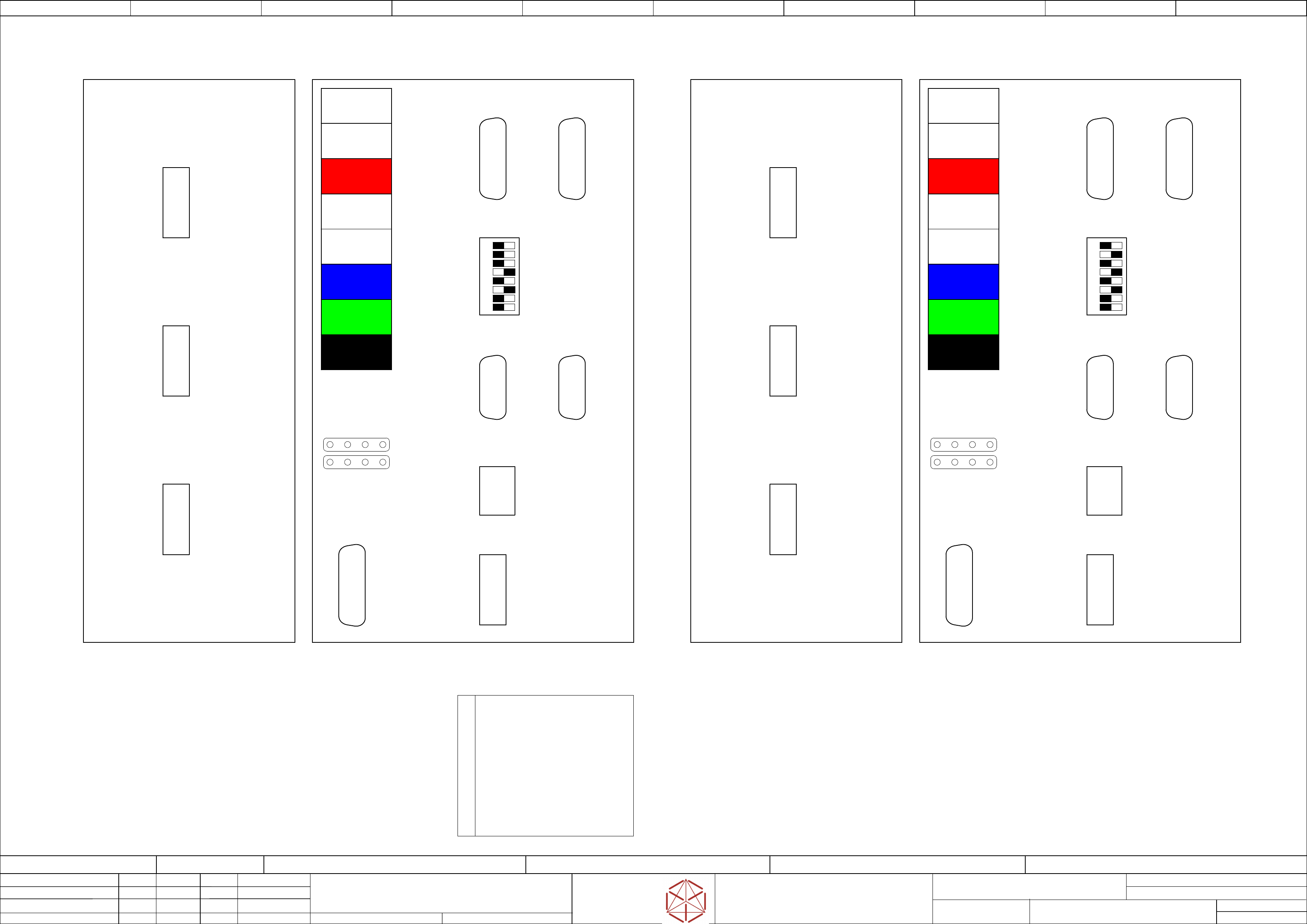
Function: Overview
==OV=SX12_V3+GA/26
drawing number:
03055284-030102LE3
03112097-010101GE4
Cable-harness
GmbH & Co KG
ASM
Assembly Systems
Copyright reserved
Ed.
Original
Schnedlitz
Date
Date
Modification
Appr
12.12.2019
Name
starting MC-Nr.: 2018/Q3 G. Pingist
Size DIN A2
Sheet
26
/
3
Note:
In 1-gantry-machines the MGCU2 is not used.
FDB
MGCU2
FDB
diagnose
FDB head
gantry 1
Option
3D Sensor
X2sp
DC link
voltage
24V,
PowerFail,
EmergencyStop
X1sp
MGCU1
(rear view)
ONOFF
8
1
DIP
Switch
Type
MGCU-3 03103477
A1 axis
X73Osc
X74Usc
X72Usc
FDB SMY
gantry 1
X73Usc
X3sp
A3 axis
X6sp
A2 axis
X4sp
MGCU1 (gantry 1)
A2_PM_ON
A1_PM_ON
A3_END
ERROR
A2_END
A1_END
A3_PM_ON
READY
LED
display
(front view)
MGCU1
X5Usc
not used not used
not
used
ONOFF
8
1
DIP
Switch
X
motor
gantry 1
Y2
motor
gantry 1
GCAN MCAN
CAN1CAN2 CAN2 CAN1
X1Usc
X1Osc X5Osc
X53sc
X71Ouc
X72Ouc
X74Ouc
X71Uuc
not used
not used
FDB SMX
gantry 2
FDB
MGCU1
Y1
motor
gantry 1
FDB head
gantry 2
Option
3D Sensor
X2up
DC link
voltage
24V,
PowerFail,
EmergencyStop
X1up
MGCU2
(rear view)
Type
MGCU-3 03103477
A1 axis
1
2
3
4
5
6
7
8
GANTRY_ID_0
GANTRY_ID_1
GANTRY_ID_2
H_GANTRY_ENABLED
MGCU_MODE_DISABLE
FDB_UHM_LINK_ENABLE
S0
S1
DIP switch description
X73Ouc
X71Osc
X74Uuc
X72Osc
X72Uuc
FDB SMY
gantry 2
FDB
diagnose
X73Uuc
X3up
A3 axis
X6up
A2 axis
X4up
MGCU2 (gantry 2)
A2_PM_ON
A1_PM_ON
A3_END
ERROR
A2_END
A1_END
A3_PM_ON
READY
LED
display
(front view)
X74Osc
X5Uuc
not used not used
not
used
Y1
motor
gantry 2
X
motor
gantry 2
Y2
motor
gantry 2
GCAN MCAN
X71Usc
not used
X1Uuc
MGCU2
X1Ouc X5Ouc
not used
X53uc
FDB SMX
gantry 1