FCS300-R-2LT-H-Manual-1.pdf - 第2页
FCS300-R-2LT-H ( 163-03534) Complete Manual Conformal Coating System Thank you for purchasing the coating syst em from PVA. Before attempting to operate the unit, we recommend that you ta ke a few minutes and read the fo…
FCS300-R-2LT-H
MANUAL COATING SYSTEM
Version: 163-03534
Operation Manual
6 CORPORATE DRIVE
HALFMOON, NY 12065
PHONE: 518-371-2684
FAX: 518-371-2688
info@pva.net
www.pva.net
FCS300-R-2LT-H (163-03534)
Complete Manual Conformal Coating System
Thank you for purchasing the coating system from PVA. Before attempting to
operate the unit, we recommend that you take a few minutes and read the following
operation and setup manual. This will assist in familiarizing you with the product and
ensure a successful installation.
As always, if any questions or problems arise, do not hesitate to contact PVA’s
Service Department for support. This department can be reached at PVA headquarters by
telephone at (518) 371-2684.
Again, thank you for your purchase, and we look forward to assisting you in the
future as you continue to improve your dispensing processes.
Theory of Operation
This manual conformal coating system is designed to allow operators to utilize
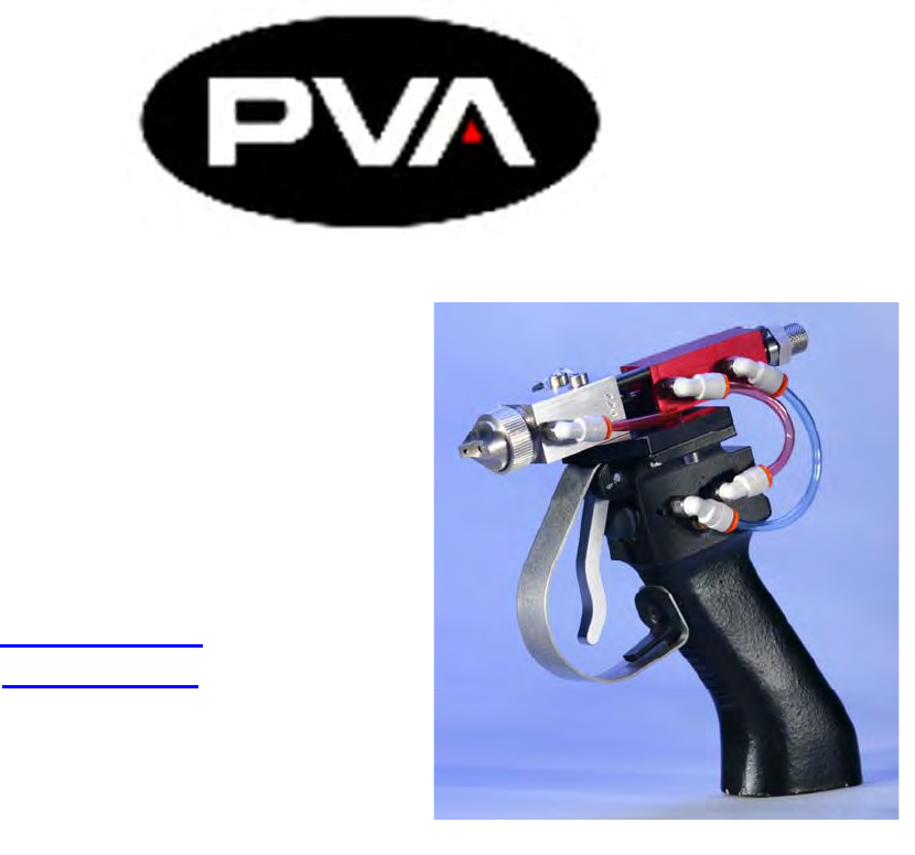
PVA’s high quality spray valve technology in a hand held applications. The system utilizes
a small 2-Liter bottle pressure tank to hold fluid that can be placed on a bench top or on the
floor to feed the valve. An FCS300-R spray valve is mounted to a pneumatic trigger handle
which allows the operator to easily articulate the valve over the part and utilize the trigger
activate the spray.
When the trigger is depressed, the valve will activate to begin fluid flow and
simultaneously turn on the atomizing air in order to spray the coating to the substrate. As
soon as the trigger is released, the flow of fluid and atomizing air will cease.
The system is designed with Stainless Steel components and a UV safe, Teflon
fluid line to provide the greatest level of compatibility with a wide variety of fluids.
Chemistries that can be used in this system include, but are not limited to Acrylics,
Urethanes, Silicones, Epoxies, Solvent basted coatings, etc.
All wetted components of the system include:
- 303, 304 stainless steel
- Teflon
- Kalrez
Safety
Due to fluid contents being under pressure eye protection is recommended for
operators. Refer to MSDS sheets on fluid being dispensed for and other precautions.
A grounding wire should be connected to the stainless steel pressure tank to remove esd.
Setup
Refer to assembly drawing 163-03534 for part reference numbers.
1. Connect the system as outlined in the assembly drawing. Being sure the fluid lines
are tightly crimped in the fluid compression fittings and air lines are secure in the
quick connect fittings.
2. Connect main air to the quick connect air fitting of the fluid tank (9) and fitting
(1) of the main air regulator feeding the valve handle.
System Operation
Initial Startup
1. First, be sure the quick air shutoff valve (red handle) of the pressure tank (9) is
turned to the Ext. position so that no air pressure is being supplied to the tank.
Note: Be sure the pressure gauge reads zero before proceeding to the next step.
2. To load fluid into the system, evenly unthread the three handles on top of the tank
until they are loose from the tank top.
Note: The handles will remain connected to the tank lid.
3. Slowly remove the tank lid assembly from the tank body.
4. Place a full bottle of fluid inside the center of the tank with the cap removed.
5. Replace the lid assembly onto the tank, being sure the dip tube that is connected
to the center of the lid inserts into the fluid bottle.
6. Tighten the three handles down evenly for air tight seal.
7. Adjust the pressure on the air regulator (2) feeding the valve handle to 80 psi.
8. Depress the trigger on the handle (15) to cycle the valve open and closed. You
should hear the solenoid actuating inside the handle and will be able to see the
center needle of the spray valve (13) moving back and forth.
9. Adjust the pressure on the atomizing air regulator (20) between 2-3psi for startup.
Note: This pressure will only activate when the trigger of the handle (15) is
pressed.
10. To begin flow of fluid to the valve, open the quick air shutoff valve (red handle)
on the pressure tank (9) and adjust the air regulator to achieve the desired fluid
flow rate.
Note: To begin, start off with a low pressure (5psi.) and increase as necessary.
11. Hold the valve (13) and trigger handle assembly (15) aiming it in a direction
where the fluid can be purged.