SJ00DCB01-17E_mail.pdf - 第2页
2 1 Saki Corporation Saki Corporation Line Scan T echnology Our Line Scan T echnology is Changing the Game… Saki's 2D AOI systems employ its proprietary , ingenious line scan technology and coaxial overhead lighting…
System Descriptions and Specifications
2D AOI Lineup
Unique, Innovative and Accurate Inspection Technology
21 Saki CorporationSaki Corporation
Line Scan Technology
Our Line Scan Technology is Changing the
Game…
Saki's 2D AOI systems employ
its proprietary, ingenious line
scan technology and coaxial
overhead lighting, combined
with a revolutionary imaging
system and simple transport
mechanism, providing the
best choice for manufacturers
looking for highly accurate,
highly reliable, high-speed
inspection.
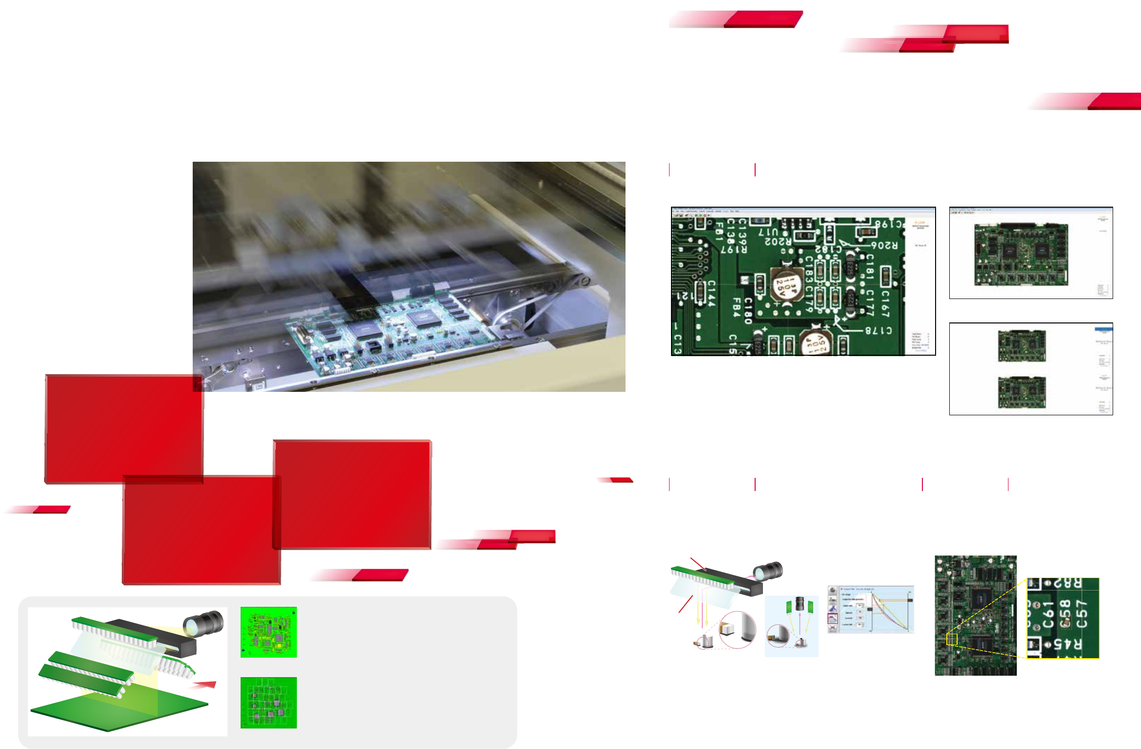
Line Scan Method: Entire image
capture in one rapid motion
Saki 2D AOI systems use a unique line-array
CCD camera to capture the entire PCB image for
each inspection. The speed of image capture is
unaffected by the number of components on the
PCB, as is the case with conventional FOV-type
AOI systems. Saki's Line Scan Technology is
the backbone of our 2D AOI systems, producing
accurate and reliable inspection data at high speeds.
Saki continually updates it software, applying the latest image
processing technology and image analysis techniques,to bring
significant performance and speed improvements to each new version.
Newer software versions are backward compatible with older hardware,
enabling the user to upgrade older systems to be compatible with new
software versions. This provides users the ability to keep their Saki 2D
AOI systems up-to-date with new inspection algorithms and libraries,
and provide reduced programming time and faster production ramp-up,
while keeping support issues to a minimum.
Saki's unique Coaxial TopLight illumination projects light
perpendicular to the surface, eliminating shadowing from other
objects on the surface. Coaxial TopLight is the best lighting for
solder fillet inspection, due to the difference in reflection when a
fillet is formed, and when it is not.
(*1) Using BF-Tristar II (10 µm resolution). Excluding board transfer time.
(*2) Using BF-Frontier II (18 µm resolution). Excluding board transfer time.
Take advantage of Saki's full PCB scanning to
inspect for stray components, solder balls, and/
or foreign materials across the entire surface.
Eliminating these defects improves the quality of
production while reducing the PPM failure level.
FOV Method: Captures one
camera field-of-view at a time.
Technology 01
Technology 02 Technology 03
Evolutionary Software
Coaxial TopLight
Whole Area Inspection
Including a growing number of rich inspection algorithms
Applying Saki's Unique Coaxial
TopLight Illumination
ECD - extra components, solder
balls and foreign objects detection
Half Mirror
Telecentric Lens
Coaxial TopLight
Ring Light
Single-Lane Mode
FUJIYAMA
integrated
algorithm which inspects 5
aspects of solder-side llets
Dual-Lane Mode
"What is Line Scan Technology?"
Fast, Accurate, Reliable
Fast
- To meet the needs of ultra high-
speed production, Saki introduces a new
camera and lighting system that
enable full image capture of an M-size
board in 5 seconds(*1), and an L-size
board in 5 seconds(*2). Ultra high-speed
dual-lane inspection is also available,
doubling throughput.
ACCURATE
-
Saki's new vibration-free
line scan mechanism is unaffected by
mechanical noise
produced
by adjacent
production equipment, with very low false
failure rates and accurate inspection data.
RELIABLE
- All Saki 2D AOI systems -
both single-lane and dual-lane models
- are built with the same robust and
simple transport mechanism, and are
housed in a compact footprint, thereby
providing years of reliable and productive
operation.
43 Saki CorporationSaki Corporation
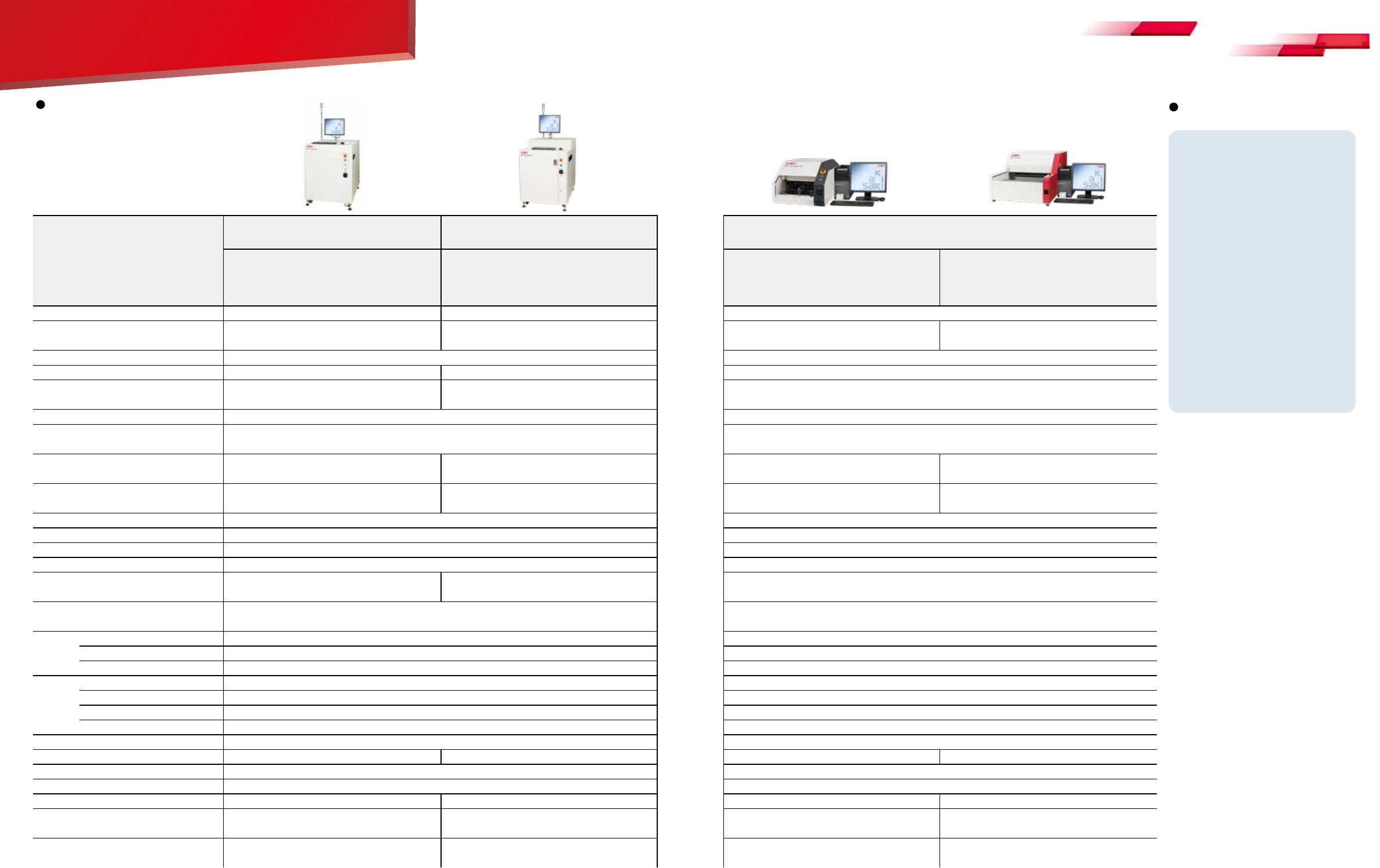
Model Lineup
Model Name
Inline, Double-sided
2D Automated Optical Inspection Systems
Inline
2D Automated Optical Inspection Systems
Benchtop
2D Automated Optical Inspection Systems
Inline AOI using Line Scan Technology to inspect
both PCB sides in one pass.
BF-Tristar
II
L-Size PCB Global Model for High-speed Inspection
of PCBs L-size to S-size.
BF-Frontier
II
Accurate, High-speed Performance
in a Smaller Desktop Model
BF-Comet18
Accurate, High-speed Performance
in a Benchtop Model for L-size PCBs.
BF-Sirius
Resolution
10 µm 18 µm 18 µm
Board Size
50 x 60 to 250 x 330mm,
2 x 2.4 to 10 x 13 in.
50 x 60 to 460 x 500mm,
2 x 2.4 to 18 x 20 in.
50 x 50 to 250 x 330mm,
2 x 2 to 10 x 13 in.
50 x 50 to 460 x 500mm,
2 x 2 to 18 x 20 in.
Board Thickness
0.6 to 3.2mm, 24 to 126 mils 0.6 to 2.5mm, 24 to 100 mils
Board Warpage
+/- 1mm, 40 mils +/-2mm, 80 mils +/-2mm, 80 mils
PCB Clearance
Top: 30mm, 1.18 in.
(*4)
Bottom: 30mm, 1.18 in.
(*4)
Top: 40mm, 1.57 in.
Bottom: 40mm, 1.57 in.
Top: 40mm, 1.57 in.
Bottom: 60mm, 2.36 in.
Rotated Component Support
Available from 0 to 359˚ (1˚ resolution)
Available from 0 to 359˚ (1˚ resolution)
Inspection Categories
Presence/Absence, Misalignment, Tombstone, Inverted, Polarity, Bridge, Foreign material.
Absence of solder, Insufficient solder, Lifted lead, Lifted Chip, and Fillet defect (*3)
Presence/Absence, Misalignment, Tombstone, Inverted, Polarity, Bridge, Foreign material.
Absence of solder, Insufficient solder, Lifted lead, Lifted Chip, and Fillet defect
(*3)
Tact Time
(based on PCB Size)
For 250 x 330mm size board: (*1)
Approx. 16 sec.
For 460 x 500mm size board: (*1)
Approx. 13 sec.
For 250 x 330mm size board: (*1)
Approx. 11.5 sec.
For 460 x 500mm size board: (*1)
Approx. 14 sec.
Scanning Time
(based on PCB Size)
For 250 x 330mm size board:
Approx. 5.5 sec.
For 460 x 500mm size board:
Approx. 5 sec.
For 250 x 330mm size board:
Approx. 4 sec.
For 460 x 500mm size board:
Approx. 5.5 sec.
Camera
CCD Line Sensor Camera CCD Line Sensor Camera
Lighting
LED Lighting LED Lighting
Conveyor System
Flat Belt Conveyor ―
Conveyor Height
900 +/-20mm, 36 +/-0.8 in. ―
Conveyor Width Adjustment
Automatic
Manual
(Automatic Width Adjustment is Optional)
―
Operating System
Windows 10 IoT Enterprise
2015 LTSB 64 bit English Version
Windows 10 IoT Enterprise
2015 LTSB 64 bit English Versionl
Optional
System
BF-Editor
✓ ✓
BF-RP1
✓ ✓
BF-Monitor
✓ ―
Options
2D Barcode Reading
✓ ✓
Journal Printer
✓ ✓
OK/NG Signal I/O
✓ ✓
Conformal Coating
Inspection
✓ ✓
Electrical Requirements
Single-phase ~100-120/200-240V +/-10%, 50/60Hz Single-phase ~ 100 - 120/200 - 240V +/- 10% , 50/60Hz
Power Consumption
800VA 750VA 400VA 700VA
Air Requirement
0.5MPa, 5L/min (ANR) ―
Operating Environment
15 (59F) to 30 (86F)℃ / 15 to 80% RH (No Condensation) 15 (59F) to 30 (86F)℃ / 15 to 80% RH (No Condensation)
Noise Level
59.7 dB 58.3 dB 56.5 dB 60.5 dB
Dimensions
850 x 1295 x 1130mm,
33.5 x 51 x 45.5 in.
850 x 1340 x 1230mm,
33.5 x 52.8 x 48.4 in.
580 x 850 x 452mm,
22.8 x 33.5 x 17.8 in. (*2)
800 x 1280 x 600mm,
31.5 x 50.4 x 23.6 in. (*2)
Weight
Approx. 450 kg, 992.1 lbs Approx. 450 kg, 992.1 lbs
(Un-crated)
Approx. 80 kg, 176.4 lbs
(Un-crated)
Approx. 175 kg, 385.8 lbs
(*1) Including scanning time.
(*2) PC, Monitor, Keyboard and Mouse sold separately.
(*3) Each defect name can be arranged.
(*4) When a PCB’ s thickness and warp are 1 mm, the top clearance is 28 mm and the bottom clearance is 30 mm from the PCB surface.
2D AOI
System Option
BF-Family
Saki's BF-Family includes optional software
programs that help you make the most of
your Saki 2D AOI Investment. All BF-Family
Software programs can be connected and
linked to each other.
[BF-Editor]
O-line Programming and Debugging
- Create,
edit and debug Inspection Programs on your PC.
[BF-RP1]
Review and Repair Defects
- Install at your
Repair or Rework Station. Visually displays defects
and NG Images alongside Good Images to make
repair easier.
[BF-Monitor]
Provides Control for Multiple AOI Systems at
One Location
- Use this to manage your factory's
inspection process remotely.