Viscom_Article_SP_3D_AXI_LEDs_EPP_Europe_en.pdf - 第2页
EPP EUROPE November 2018 25 I n electronics manuf actu ring, when there is a need to examine a print ed circuit board rejected b y a customer , an anomaly in production, or a prototype that has just been dev eloped, manu…
24
EPP EUROPE November 2018
Hidden structures clearly revealed
Fast in-line X-ray
secures quality
High-quality systems for automatic optical inspection (AOI) of electronic
assemblies offer as standard features both high throughput and 3D. For
hidden solder joints, more and more electronics manufacturers want to
employ in-line X-ray systems (AXI) as well. Again, it comes down to fast
assembly handling and first-class 3D image quality. One example is the
secure detection of voids as required in manufacturing of products with
light-emitting diodes (LEDs) and other applications.
COVER
EPP EUROPE November 2018
25
I
n electronics manufacturing, when there is a need to
examine a printed circuit board rejected by a customer,
an anomaly in production, or a prototype that has just
been developed, manual X-ray (MXI) is a good choice.
How long the inspection with any optional radiation pen-
etration angle between tube and swiveling detector fin-
ally takes is not a decisive factor. Because it is separate
from the production lines, it does not impact cycle times.
However, if a one hundred percent examination of hidden
solder joints is required, in-line X-ray systems are called
for. Typical examples of components soldered in this way,
where automatic optical inspection meets its limits, are
QFNs (quad-flat no-leads package) and BGAs (ball grid
array) as well as, e.g., the increasingly miniaturized LEDs.
Concept with parallel printed circuit board
handling
In-line X-ray systems must reliably point out defects that
are invisible to the human eye; furthermore, they are con-
stantly developing to keep pace with the rising demands
for speed in electronics manufacturing. For example,
today handling times as low as four seconds can be real-
ized; as a result, up to three printed circuit boards can be
present in the 3D AXI system at the same time. In order
to keep the X-ray inspection from unnecessarily slowing
down line beat, the faster 2D and 2.5D inspections can
be combined with 3D inspections as required. 3D tech-
nology is applied where it is most efficient.
Results without interfering structures
It is helpful for the inspection to gain slice images from
volume information. Both horizontal and vertical slices
can be extracted. Because of the extremely complex
overlapping, especially with printed circuit boards popu-
lated on both sides, this capability is essential. In this
case, with a 3D reconstruction, all significant features can
be made sharply visible in clear slice images – even for
shadowing by components or on multi-layer boards.
While details of the back side are always seen in 2D X-ray
images, the 3D slice image eliminates all such interfering
structures. This greatly simplifies inspection program
generation and enables effective false call prevention. For
improved verification, planar computed tomography of a
3D AXI system can be applied to generate partial or com-
plete volumes of the inspected solder joint, which can
then be tilted, rotated and zoomed on the monitor.
COVER
Viscom AG, from Hanover, Germany,
has developed an extremely fast
printed circuit board transport
especially for in-line X-ray inspection.
Source: Viscom AG
26
EPP EUROPE November 2018
3D AXI on the example of LEDs
When LEDs are examined more closely, it is immediately apparent
that a 3D AOI on its own is not enough to guarantee high quality in
the final product. In-line X-ray provides the ideal means, especially
to precisely inspect the associated hidden solder joints. Innumer-
able application possibilities from interior lighting, streetlights, and
displays are open for LEDs, and for industrial designers, a wide lati-
tude in implementing their lighting ideas. The automotive branch in
particular was quick to recognize the potential of this technology,
which has long since established itself as the standard in vehicle
lights, flashers, and headlights. Its inherent advantages include a
long service life, high light yields, and low energy consumption.
Heat dissipation is a decisive quality feature
LEDs emit not only light, but heat as well. Quick dissipation of this
heat is critical for their longevity. The electronics association IPC has
not specified any standards for heat dissipation in their acceptance
criteria. These standards state only that for components with con-
nections to heat sinks on their bottom sides, the criteria
for the hidden areas of the solder joints on the thermal
level must be determined by agreement between user
and manufacturer. For the heat transition layer, these
criteria depend on process and design, whereby the com-
ponent manufacturer‘s application notes, solder cover-
age, pores, solder height, etc., must be taken into ac-
count. Formation of pores and bubbles in the thermal
layer when these component types are soldered is nor-
mal. However, hollow spaces in the solder joints (voids) in
particular can prevent optimal dissipation of heat from
chips and semiconductor component barrier layers. The
life span (operating hours), wavelength (color), and even
the light yield (brightness) of the LEDs are strongly de-
pendent on the barrier layer temperature.
High efficiency under strict requirements
Especially in the automotive industry, manufacture and
quality control of printed circuit boards assembled with
LEDs are often sourced to EMS providers (Electronic
Manufacturing Services). They must meet the strict
requirements of their ordering customers and at the
same time, be as efficient as possible to stay competi-
tive. Here, brand manufacturers specify very precisely
just how high a percentage of voids in solder joints is ac-
ceptable. Process ovens with vacuum chambers and
other means can help prevent voids. Those that do form
can be very clearly identified with cutting-edge 3D X-ray.
While a flexibly applicable manual system is adequate for
random inspections, one hundred percent, fully auto-
matic inspection is performed by a system in the production line.
This way, voids can be completely recorded and analyzed, even
while hidden from an outside view.
X-ray and optical inspection supplement each other
Nevertheless, the importance of 3D AOI in inspecting LEDs is by no
means overshadowed. Especially in automotive applications, there
are very specific requirements for the positioning and alignment of
the components. Detecting defects such as minimum non-coplanar-
ity of the ever smaller LED components depends on reliable
measurement values. To support the absolute precision and repeat-
ability of 3D AOI, an exactly manufactured height gauge – measured
with high precision instruments by a specialized laboratory and cer-
tified – can be used as a target standard. Tilted components can be
detected with 3D AOI very well; precise measurements are also
achieved for rotations and X/Y offset. Thus, the AOI also makes a
decisive contribution to quality assurance.
Different inspection methods in the
optimized process
3D AOI and 3D AXI have been optimally incorporated in a single ma-
chine for many years now. Printed circuit boards move quickly and
nearly simultaneously between the two inspection sections and the
combination of different inspection methods can be versatilely ad-
COVER
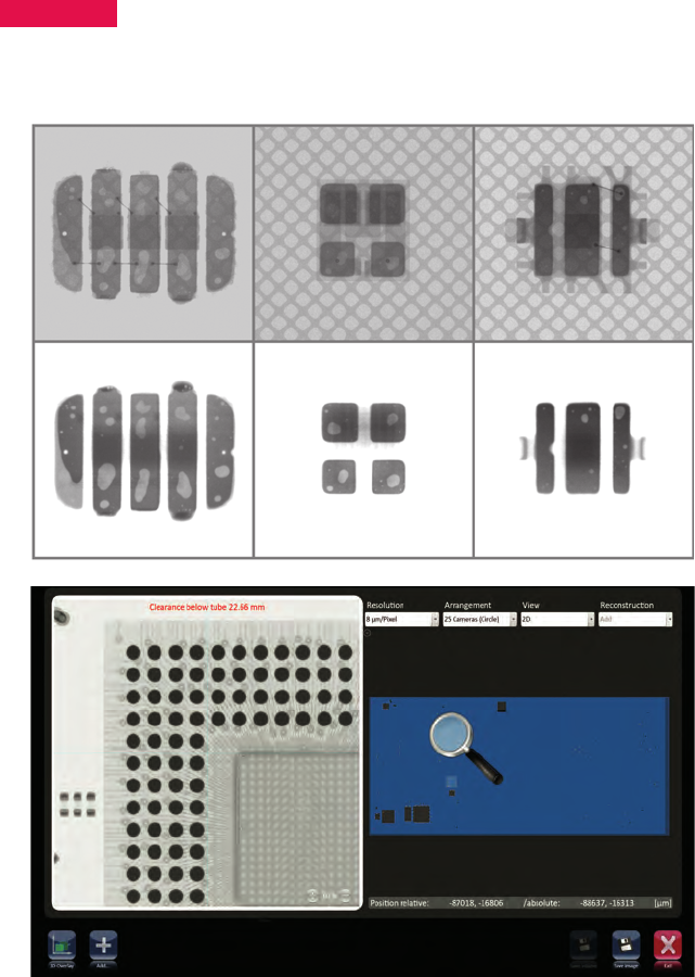
Details of a BGA shown with the X-ray viewer of Viscom‘s operating software, vVision.
Source: Viscom AG
Comparison of 2D AXI (top row) and 3D AXI slice images (bottom row) with
three different LEDs as examples. The 3D AXI image quality convinces with
excellent void recognizability.
Source: Viscom AG