OM-1352-003_w.pdf - 第75页
10-2 Tg1357-ID-SO 10.2 I/O Check T able of Drawer Connector Pins 10.2 I/O Check T able of Drawer Connector Pins Drawer Connector 1 (Low Address Side) T able 1 1 Pin No. Flux Dispensing Unit Ref.: T ape Feeders Signal Nam…
10-1
Tg1357-ID-SO
0703-003 (M806WFX--0102)
10. Material
10. Material
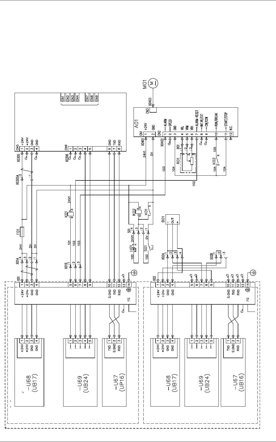
10.1 Electrical Circuit Diagrams
Flux Dispensing Unit Circuit Diagram
Drawer Connector for Feeder
GXH Main Body Side
Connection Confirmation Signal [OUT]
Not Used
(Feeder Base)
Feeder Power
Distribution
Feeder Base I/O
Feeder Base Serial
Communications
Feeder Power
Distribution
Feeder Base I/O
Feeder Base Serial
Communications
(Feeder Base)
Drawer Connector for Feeder
Rotation Start
Alarm Reset
Driver Alarm
Communications
Ready
Feeder Connec-
tion Check
Not Used
Not Used
Rotation Detection
Remainder Detection
Feeder Connec-
tion Check
Rotation Detection Sensor
Flux Transfer Device
Servoamplifier
Lane 1 Feed Command [IN]
Lane 2 Feed Command [IN]
Ready Signal [OUT]
Connected Check Signal
(For Communications Confirmation) [OUT]

10-2
Tg1357-ID-SO
10.2 I/O Check Table of Drawer Connector Pins
10.2 I/O Check Table of Drawer Connector Pins
Drawer Connector 1 (Low Address Side) Table 11
Pin No.
Flux Dispensing Unit
Ref.: Tape Feeders
Signal Name Description
1 +24V 24 V DC Power Supply
←
2 +24V 24 V DC Power Supply
←
3 GND GND of 24 V DC Power Supply
←
4 GND GND of 24 V DC Power Supply
←
5 IN: Rotation Start/Stop ON (L): Rotation OFF (H): Stop
(Connection with DC Motor Driver)
IN: Lane 1 Feeding
Command
6 IN: Alarm Reset ON (L): Set
(Connection with DC Motor Driver)
IN: Lane 2 Feeding
Command
7 OUT: DC Motor Drive
Alarm
ON (L): Normal
OFF (H): Abnormal
(Connection with DC Motor Driver)
OUT: Feeding Ready
8 OUT: Communications
Ready
RS232C Communications Available
←
9 OUT: Connection Check:
GND Return
Check of Connection with Feeder
Base Slot
←
10 GND (RS232C) Signal GND
←
11
TXD (RS232C) Transmission Line
←
12 RXD (RS232C) Reception Line
←
13 NC Not Used
←
14 FG (Frame Ground) Case Grounding
←
Drawer Connector 2 (High Address Side) Table 12
Pin No.
Flux Dispensing Unit
Ref.: Tape Feeders
Signal Name Description
1 +24V 24 V DC Power Supply
←
2 +24V 24 V DC Power Supply
←
3 GND GND of 24 V DC Power Supply
←
4 GND GND of 24 V DC Power Supply
←
5 IN: Reserved Reserved IN: Lane 1 Feeding
Command
6 IN: Reserved Reserved IN: Lane 2 Feeding
Command
7 OUT: Rotation Detection Duty Ratio 1:1 of ON (L)/OFF (H) OUT: Feeding Ready
8 OUT: Reserved Reserved OUT: Communications
Ready
9 OUT: Connection Check:
GND Return
Check of Connection with Feeder
Base Slot
←
10 GND (RS232C) Signal GND
←
11
TXD (RS232C) Transmission Line
←
12 RXD (RS232C) Reception Line
←
13 NC Not Used
←
14 FG (Frame Ground) Case Grounding
←
0703-003
10-3
Tg1357-ID-SO
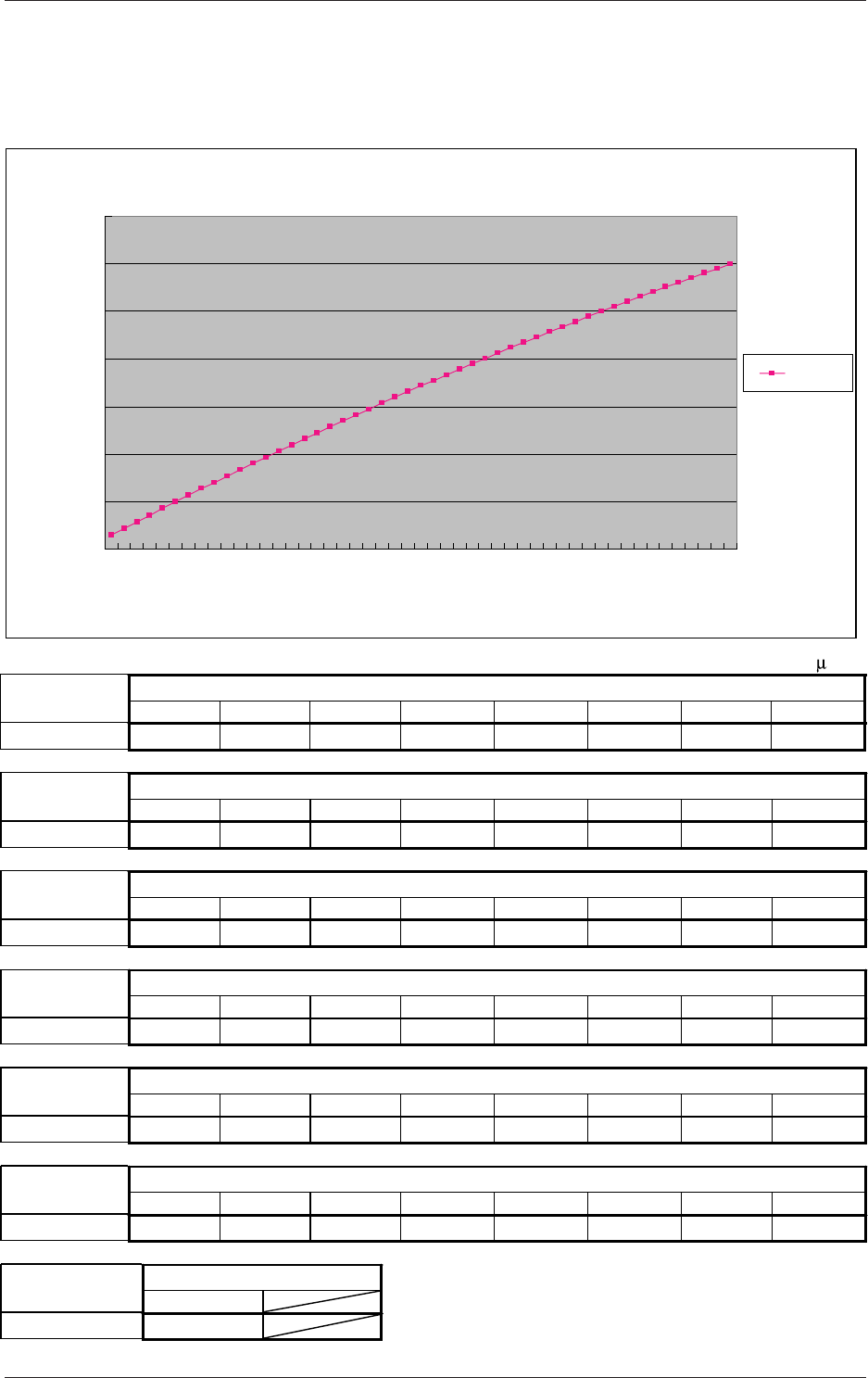
10.3 Relation between Flux Forming Film Thickness and Specified Values for Squeegee
10.3 Relation between Flux Forming Film Thickness and
Specified Values for Squeegee
Specified Values of Squeegee
Specified Values of Squeegee
Specified Values of Squeegee
Specified Values of Squeegee
Specified Values of Squeegee
Specified Values of Squeegee
Specified Values of Squeegee
Unit:
m
Flux Viscosity
(9 to 20 Pa/s)
20 30 40 50 60 70 80 90
100 110 120 130 140 150 160 170
180 190 200 210 220 230 240 250
260 270 280 290 300 310 320 330
340 350 360 370 380 390 400 410
420 430 440 450 460 470 480 490
500
Formed Film Thickness
Flux Viscosity
(9 to 20 Pa/s)
Formed Film Thickness
Flux Viscosity
(9 to 20 Pa/s)
Formed Film Thickness
Flux Viscosity
(9 to 20 Pa/s)
Formed Film Thickness
Flux Viscosity
(9 to 20 Pa/s)
Formed Film Thickness
Flux Viscosity
(9 to 20 Pa/s)
Formed Film Thickness
Flux Viscosity
(9 to 20 Pa/s)
Formed Film Thickness
15 to 20 20 to 25 25 to 30 25 to 30 40 to 45 50 to 55 55 to 60 60 to 65
70 to 75 75 to 80 85 to 90 90 to 95 95 to 100 100 to 105 110 to 115 115 to 120
120 to 125125 to 130 135 to 140 140 to 145 145 to 150 150 to 155 155 to 160165 to 170
170 to 175175 to 180 180 to 185 185 to 190 190 to 200 195 to 205 200 to 210205 to 215
215 to 225220 to 230 225 to 235 230 to 240 235 to 245 240 to 250 245 to 255250 to 260
255 to 265
295 to 305
260 to 270 265 to 275 270 to 280 275 to 285 280 to 290 285 to 295 290 to 300
0
50
100
150
200
250
300
350
2
0
5
0
8
0
110
1
4
0
1
7
0
2
0
0
23
0
2
6
0
29
0
32
0
350
3
80
410
440
4
7
0
5
0
0
Formed Film Thickness (μm)
Relation between Formed Film Thickness and Specified Values for Squeegee
Specified Values (
μm) for Squeegee
Mean
Values
0703-003