cp45电脑部分判断.pdf - 第3页
6. PC Ver. Date CP45 CP45NEO 00 2004/11 O O 6-1 6-1-1) Mother Board Settin g Procedure 1-1) CPU V altage - Automatic Setting 1-2) CPU F requency Selec tion - Automatic Setting 1-3) CPU FSB Setting 1-4) ATX Power Connec t…
6. PC
Ver. Date CP45
CP45NEO
00 2004/11 O O
6-1
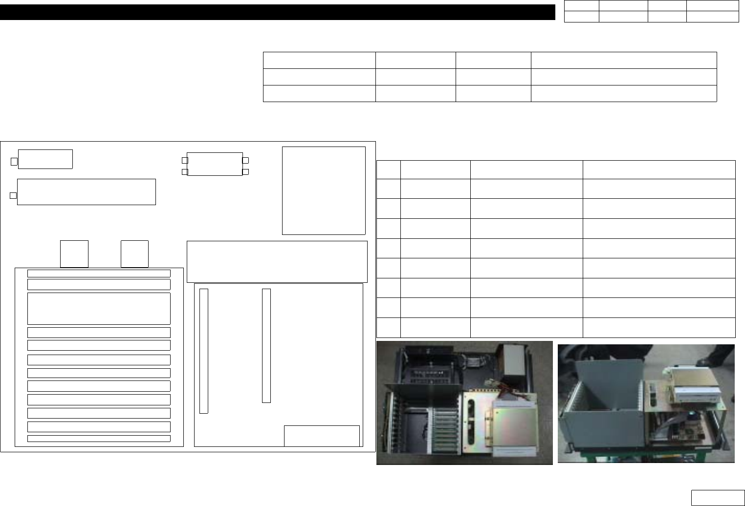
2 Kinds of PC(General PC and Industrial PC) are Used(Serial No. Used)
6-1 General PC
Fig.6-1 PC(General Type) Layout in Rack Ass'y
PS#2
VGA, MOUSE, KEY CONNECTORBRACKET
******************
NF#2
PS#2-2
PC POWER SUPPLY
PS#1
VME CPU Board(Slot1)
Vision Board(Slot2~4)
Axis 1 Board(Slot5)
Axis 2 Board(Slot6)
Axis 3 Board(Slot7)
Axis 4 Board(Slot8)
CAN Master B oard(Slot9)
Dummy Slot(Slot10)
Dummy Slot(Slot11)
Dummy Slot(Slot12)
I
S
A
I
/F
P
C
B
P
C
I
V
G
A
HDD
(Lower)
FAN
FAN
VME RACK
PC RACK
PC Mother Board
No. Code Item Spec.
1 J4801013A MOTHER BOARD COMMATE A370VB
2 J4901008A CPU [INTEL CELERON733Mhz]
3 J3105018A CPU FAN [A50933-003]
4 J5101021A HARD DISK DRIVER [HDS722580VLAT20]
5 J5001008A MODULE RAM [SDRAM 128M 168PIN PC133]
6 J4802012A VGA CARD [GEFORCE2 MX200 LP 32M]
7 J5103006A CDROM DRIVER [SC-152G]
8 J5502003A Y-CABLE [PC POWER]
CP45F(V) CP45NEO Remark
General PC ~ #1673 ~#252 J4801013A(Mother Board only)
Industrial PC #1674 ~ #253 ~ (Mother Board+VGA Card)
6. PC
Ver. Date CP45
CP45NEO
00 2004/11 O O
6-1
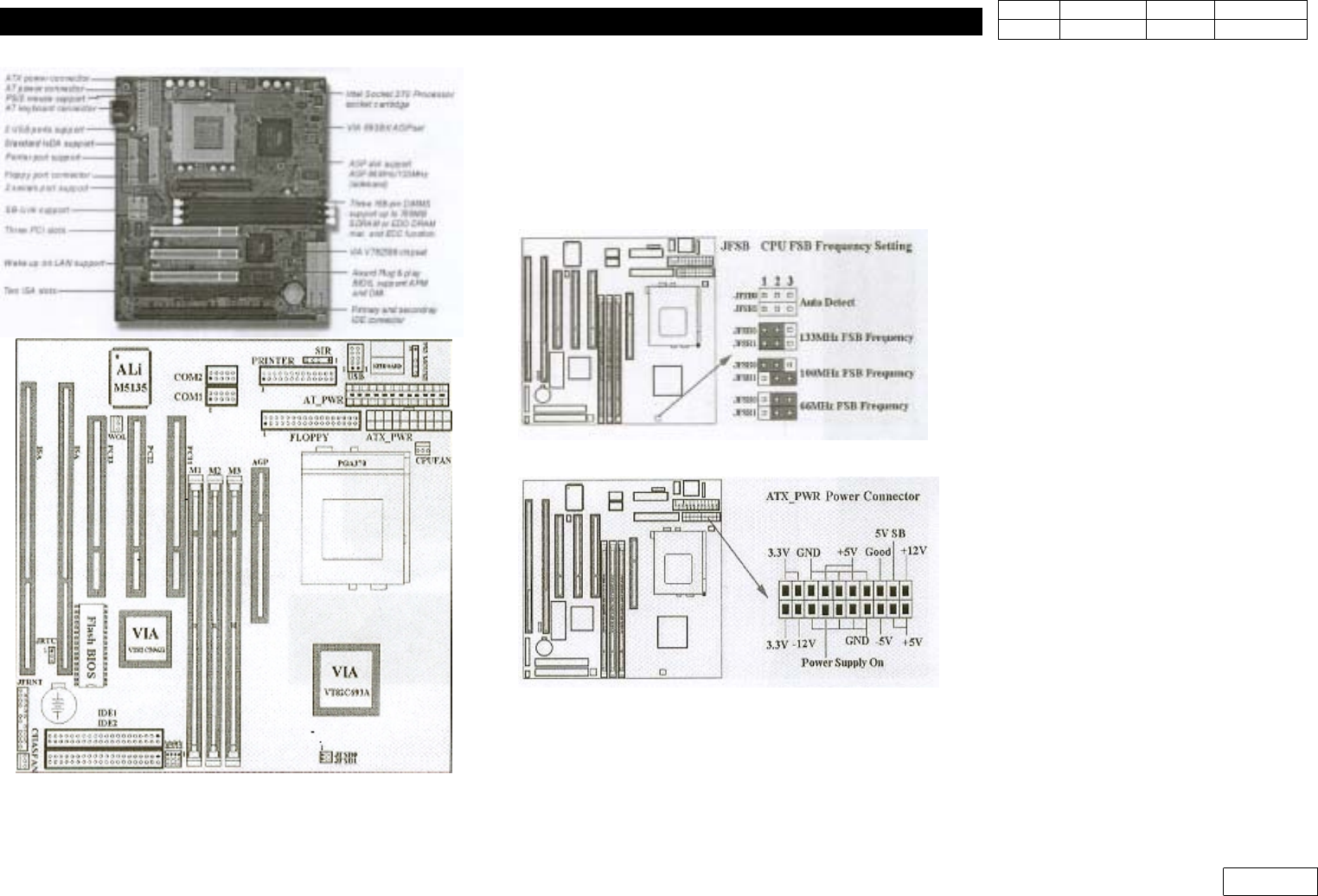
6-1-1) Mother Board Setting Procedure
1-1) CPU Valtage
- Automatic Setting
1-2) CPU Frequency Selection
- Automatic Setting
1-3) CPU FSB Setting
1-4) ATX Power Connector(20 pin ATX_PWR)
Fig.6-1-1 Mother Board Layout
6. PC
Ver. Date CP45
CP45NEO
00 2004/11 O O
6-1
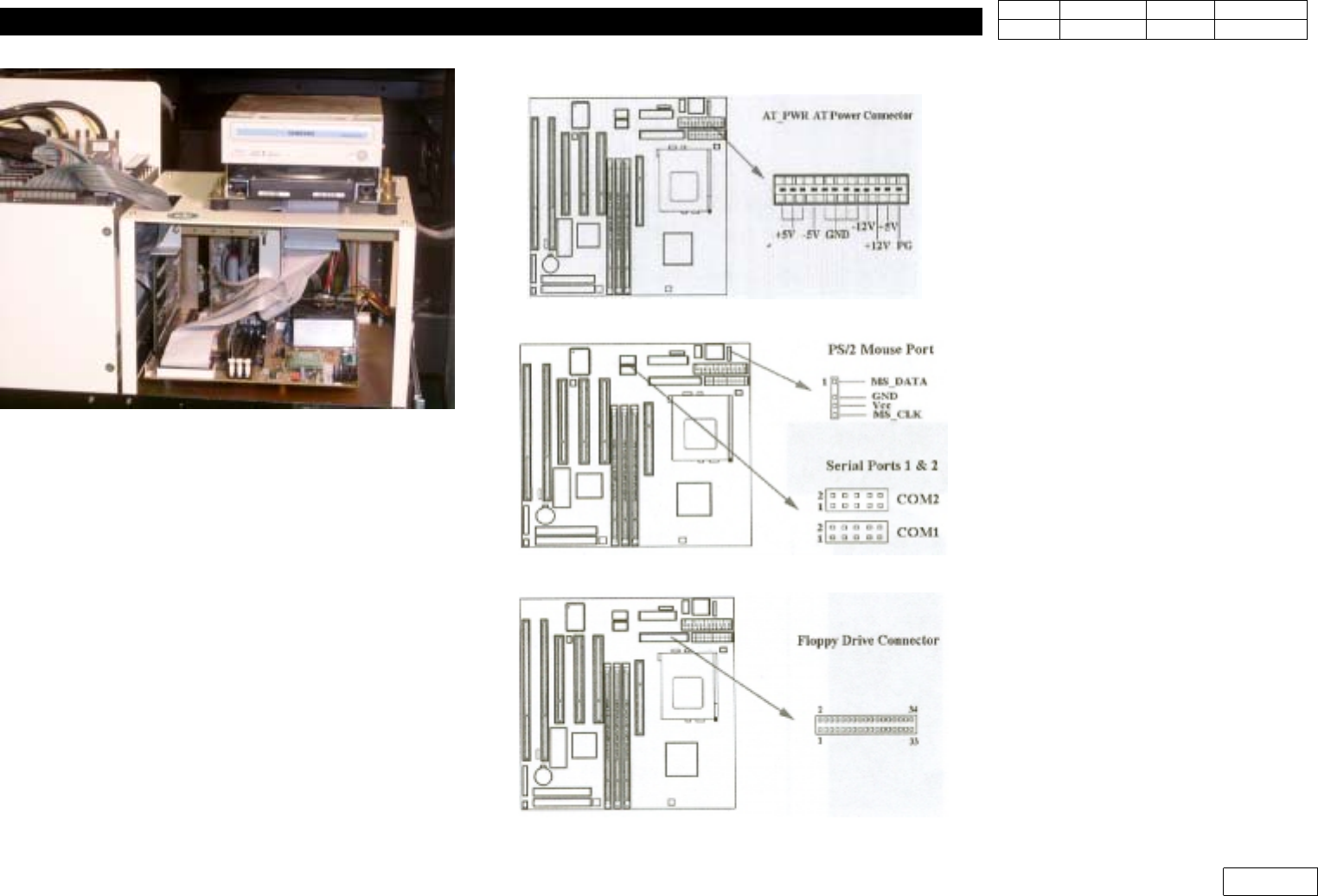
1-5) AT Power Connection(12 pin AT_PWR)
1-6) PS/2 mouse port & Serial port(10pin)
1-7) Floppy Disk Driver(12 p in)
Fig.6-1-1-1 General P C